Industry news
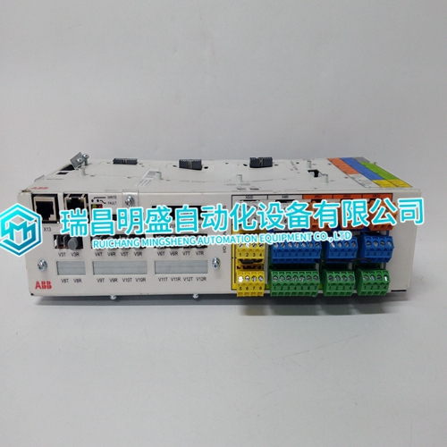
BCU-12 3AUA0000110430 Module of the breakthrough
BCU-12 3AUA0000110430 Module of the breakthrough
You can install fiber-optic FA-bus type 2 modules in both main and subunits and connect them with fiber-optic cables. This enables distributed arrangement of remote I/O points, increase in the number of I/O points, and control of I/O modules via high-speed, noiseimmune communication.The maximum number of subunits that can be connected is 7. Subunit numbers are determined depending on the setting of the rotary switch on the fiber-optic FA-bus type 2 module mounted to a subunit.Example of increasing the number of I/O points using FA-bus type 2 modules As with fiber-optic FA-bus type 2 modules, the number of I/O points can be increased using FA-bus type 2 modules. FA-bus type 2 modules use shielded twisted-pair cables for the connection between subunits. (The cable length is restricted compared to fiber-optic FA-bus type 2 modules.)
Restrictions on Module Location
- A CPU module installed in slot 1 serves as the main CPU module. - CPU modules installed in slots 2 to 4 serve as the add-on CPU modules. - I/O modules may also be installed in slots 2 to 4. No add-on sequence CPU module or add-on BASIC CPU module can be installed in a slot with a slot number greater than those of the I/O modules. - In an application where two or more CPU modules are installed, no I/O module can be installed between any two CPU modules.*1: Indicates the maximum number of modules that can be used in total including the main CPU module when CPU modules with the same model name as the main CPU module are used as add-on CPU modules. *2: A maximum of two modules can be installed in this combination. *3: The combination of F3SP7-N + F3SP7-N + F3SP21 (25, 35/ F3BP20, 30) is not possible.
Restrictions on I/O Module Installation
Table A1.3 shows the types of modules that each CPU module can access directly, as well as the maximum number of modules of each type that can be installed at the same time. The maximum number referred to here means a limit to the quantity of modules when a multiple of the same I/O module is installed. - “9’’ identifies an I/O module that can be installed without limitation on its quantity. - “–’’ identifies an I/O module to which the CPU module in question cannot have direct access. - Each numeral means the maximum number of I/O modules that can be installed, provided that they are of the same type. In addition to the restrictions on the quantity of each I/O module, there are system-wide limitations to the quantity of I/O modules that can be installed. For more information, see Appendix A1, “System-wide Restrictions on Module Installation.” In the table below, modules with shaded module names must be installed in the main unit.