Industry news
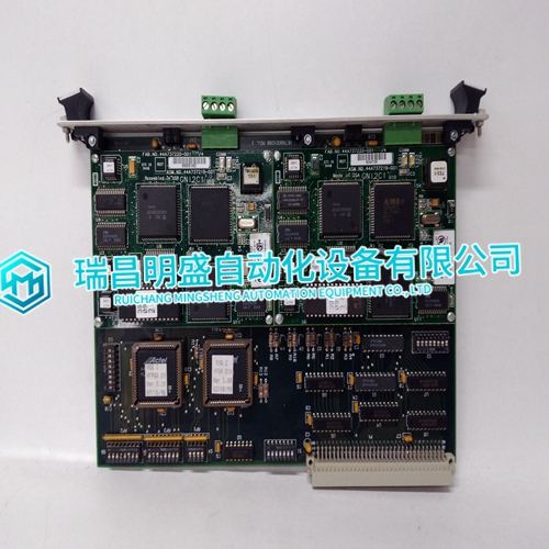
HE700GEN200 Module USES process
HE700GEN200 Module USES process
In a dusty location, either hermetically seal the panel enclosure, or purge the panel enclosure with clean air ensuring the interior of the panel enclosure is pressurized slightly higher than its surroundings to prevent the intrusion of outside dust.Mounting Positions The FA-M3 module is designed with natural air cooling heat design considerations. Install the FA-M3, orientated so that the LED display is at the top and the air outlets are at the top and bottom.When mounting the FA-M3 on a DIN rail, attach a rail mount kit to the back of the controller. For the rail mount kit, purchase either Model T9031AP (for F3BU04, F3BU06 and F3BU05 base modules) or Model T9031AQ (for F3BU09 and F3BU13 base modules) separately. Note that F3BU16-0N, F3BU09-2N and F3BU13-2N are not designed for mounting on a DIN rail. Installing a Rail Mount Kit A rail mount kit comprises two component parts that are used in combination.The number of components needed is shown below. (A) X 1 and (B) × 2 (for F3BU04, F3BU06 and F3BU05 base modules) (A) X 2 and (B) × 4 (for F3BU09 and F3BU13 base modules)
Mounting on the DIN Rail
Mount a base module on the DIN rail as follows.- Ensure that the base module is securely attached to the DIN rail. - Do not use the DIN rail to install the FA-M3 system in an environment where it would be subjected to excessive vibration, impact or mechanical load as it may fall off the DIN rail. - Secure both ends of the base module so that it would not slide along the base module.Removing latch (A) Release the latch on the front of the base module by hand and remove it. Removing latch (B) Insert a flat-blade screwdriver between the base module and the latch and turn it slightly to remove the latch Pull hook (A) in the direction of the arrows before pulling the module toword you (Hooks can be easily disengaged with a flat-blade screwdriver)Figure A3.4 shows how to attach the module to the base module. First hook the anchor slot at the bottom of the module to be attached onto the anchor pin on the bottom of the base module. Push the top of the module toward the base module until the anchor/release button (yellow button) clicks into place
Detaching the Module
To remove the module from the base module, reverse the above operation. Press the anchor/release button (yellow button) on the top of this module to unlock it and tilt the module away from the base module.If the module is used in intense vibration environments, fasten the module with a screw. Use screws of type listed in the table below. Insert these screws into the screw holes on top of the module and tighten them with a Phillips screwdriver.Do not apply excessive load on the module. Be particularly aware that a downward load of 5 kg or more applied on the connector head (at a position 55 mm from the front side of the module) may cause the module to fall off from the base module.- The depth of the installed module and the base module together is approximately 90 mm. An additional length should be allowed for cable bending however, if any cable with connectors is attached to the controller.