Industry news
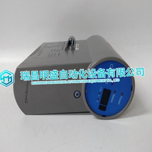
HONEYWELL CC-PCNT02 Card use guide
HONEYWELL CC-PCNT02 Card use guide
Installation Procedure The module installation procedure includes the following steps: 1. Determine the location of the module on the vacuum chamber. 2. Attach the module’s flange/ fitting to its mating fitting on the vacuum chamber. 3. Assemble and connect the module wiring To determine the best location for the module, refer to Figure 2-1 and follow the guidelines below. • For greatest accuracy and repeatability, locate the module in a stable, room-temperature environment. Ambient temperature should never exceed 40 °C (104 °F) operating, non-condensing, or 70 °C non-operating. Bakeout temperature with the electronics removed from the module is 200 °C. • Locate the module away from internal and external heat sources and in an area where ambient temperature remains reasonably constant. • Do not locate the module near the pump, where gauge pressure might be lower than system vacuum pressure. • Do not locate the module near a gas inlet or other source of contamination, where inflow of gas or particulates causes atmospheric pressure to be higher than system atmosphere. • Do not locate the module where it will be exposed to corrosive gases such as mercury vapor or fluorine.
To minimize the possibility of leaks
with ConFlat® flanges, use high strength stainless steel bolts and a new, clean OFHC copper gasket. Avoid scratching the seal surfaces. To avoid contamination, install new metal gaskets. a. Finger tighten all bolts. b. Use a wrench to continue tightening 1/8 turn at a time in crisscross order (1, 4, 2, 5, 3, 6) until flange faces make contact. c. Further tighten each bolt about 1/16 turn. Step 3 Assemble and Connect the Wiring VCR Type Fitting: a. Remove the bead protector cap from the fitting. b. Place the gasket into the female nut. c. Assemble the components and tighten them to finger-tight. d. While holding a back-up wrench stationary, tighten the female nut 1/8 turn past finger-tight on 316 stainless steel or nickel gaskets, or 1/4 turn past finger-tight on copper or aluminum gaskets. Do not twist the module to tighten the fitting.
Connecting Cables
The cables are user-supplied. Granville-Phillips does not supply cables. Install externally shielded cables. Wiring connects to the power connector, the 9-pin I/O connector, and the DeviceNet 5-pin micro connector. See Figure 2-2, Table 2-1, and Table 2-2. • Connect the module power-supply wiring and the relay wiring to the 9-pin I/O connector. See Figure 2-2 • Connect the DeviceNet power-supply and network wiring to the DeviceNet 5-pin micro connector. See Figure 2-2 Cable to 9-pin I/O connector For the cable that connects to the 9-pin I/O connector, install shielded cable with aluminum jacket and a tinned copper braid with a minimum of 65% coverage. On the module end of the cable, install a metal housing, so the shield is continuous from the cable to the gauge housing. Do not ground the shield at the receiver or output device.
