Industry news
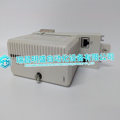
CI867K01 3BSE043660R1 Processor module USES manual
CI867K01 3BSE043660R1 Processor module USES manual
Acceptable raw cable parts: • Belden cable 9947. • Alpha cable 5110/15C SL005. Acceptable connector: • Tyco series ADK for standard 9-pin subminiature-D connectors. DeviceNet Cable For the DeviceNet cable, install raw cable that has a braided shield over the aluminum foil-shielded signal and power wires. On the module end of the cable, install a metal housing, so the shield is continuous from the cable to the gauge housing. Do not ground the shield at the receiver or output device. • Acceptable raw cable is DeviceNet shielded cable type 578 from Turck. • Acceptable connector is CM 8151-0 metal connector from Turck The Micro-Ion Vacuum Gauge Module grid supply voltages reach 180 Vdc during operation and 250 Vdc during degas cycles. Improper grounding could cause severe product failure or personal injury. Follow ground network requirements for the facility. Maintain all exposed conductors at Earth ground.
Module Power Supply
The customer supplied power supply should provide operating voltage and current to the Series 354 Micro-Ion Vacuum Gauge Module as specified in Table 2-1 and Table 2-2. Surge current is the maximum momentary current when power is first applied before the ion gauge is turned ON. Operating current is the steady-state current during normal operation with the ion gauge ON. The Micro-Ion gauge will not activate and an emission error will occur if insufficient power is supplied during Micro-Ion gauge activation.The module has been tested and found to comply with U.S. Federal Communications Commission (FCC) limits for a Class A digital device, pursuant to Part 15 of the FCC rules. These limits provide reasonable protection against harmful interference when the module operates in a commercial environment. The module generates and can radiate radio frequency energy. If not installed and used in accordance with the instructions in this manual, the module may cause harmful interference to other electrical equipment.
DeviceNet Wiring
The module has a DeviceNet 5-pin micro connector for interfacing through the customer supplied DeviceNet network cable. See Figure 2-2. The DeviceNet connection is a standard 5-pin DeviceNet receptacle that accepts a standard micro 5-pin female cable connection. Use terminals 2 (Vdc return) and 3 (24 Vdc) on the 5-pin DeviceNet micro connector for the network power supply. • The DeviceNet interface requires 24 Vdc (16 to 26.4) at 0.2 A maximum. • Maximum inrush current is 0.25 A. • Power inputs are reverse-bias protected. Grounding The module contains three separate and isolated grounds: the DeviceNet ground, the analog ground, and the chassis ground. Typical isolation between DeviceNet and chassis grounds is 1 MΩ. The module generates 180 Vdc during normal operation and 250 Vdc during Micro-Ion gauge degas.
