Industry news
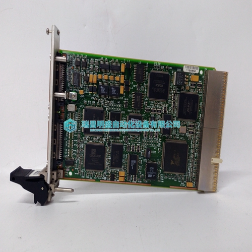
NI PXI-7344 Motion control module experiment data
NI PXI-7344 Motion control module experiment data
While holding the flange, gently pull the Micro-Ion Vacuum Gauge Module away from the gauge collar plate as shown in Figure 4-1. The gauge tube and plate will disconnect from the module. 6. Using a digital multimeter, measure the resistance of the left filament and the right filament between filament pins as shown in Figure 4-2. The reading should be approximately 0.2 Ω.7. Measure the resistance of filament pins to any other pin or gauge case as shown in Figure 4-2. The reading should be infinity. 8. Measure the resistance between Grid pins as shown in Figure 4-2. The reading should be approximately 0 Ω. 9. Measure the resistance of Grid pins to any other pin or gauge case as shown in Figure 4-2. The reading should be infinity. 10. Measure the resistance of Collector pin to any other pin or gauge case as shown in Figure 4-2. The reading should be infinity. NOTE: If the readings obtained during this procedure are not within the values specified, the gauge should be replaced. Contact a Granville-Phillips Customer Service Representative to order a replacement gauge. See Section 4.1 Service & Maintenance Guidelines on page 57 at the beginning of this chapter.
To Reassemble the Micro-Ion Gauge/Module
If the continuity check proves that the gauge is good, reassemble the gauge/module as outlined below. If replacement of the gauge is necessary, install the replacement gauge as outlined below. NOTE: The Micro-Ion replacement gauge is double-packaged at the factory for cleanroom compatibility. Handle the gauge carefully to avoid damaging the vacuum port screen after the cap plug is removed. To reduce the chance of contamination, do not remove the replacement gauge from its inner bag until you are ready to install it and connect the module to the vacuum system. Avoid contaminating the replacement gauge. Do not touch the vacuum connection port. Follow good vacuum practice. To minimize the possibility of leaks, do not scratch the vacuum connection seal surfaces. 1. Align the notches on the replacement gauge collar plate and the Micro-Ion Vacuum Gauge Module as shown in Figure 4-1. 2. Gently insert the replacement gauge and collar plate into the Micro-Ion Vacuum Gauge Module until the tube pins are inserted into the tube socket.
Service Guidelines
Some minor problems are readily corrected on site. If the product requires service, contact the MKS Technical Support Department at 1-303-652-4400 or 1-800-776-6543 for troubleshooting help over the phone. If the product must be returned to the factory for service, request a Return Material Authorization (RMA) from MKS, which can be completed at https://www.mksinst.com/service/servicehome.aspx. Do not return products without first obtaining an RMA. In most cases a hazardous materials disclosure form is required. The MKS Customer Service Representative will advise you if the hazardous materials document is required. When returning products to MKS, be sure to package the products to prevent shipping damage. Shipping damage on returned products as a result of inadequate packaging is the Buyer's responsibility. For Customer Service / Technical Support: MKS Pressure and Vacuum Measurement Solutions MKS Instruments, Inc.
