Industry news
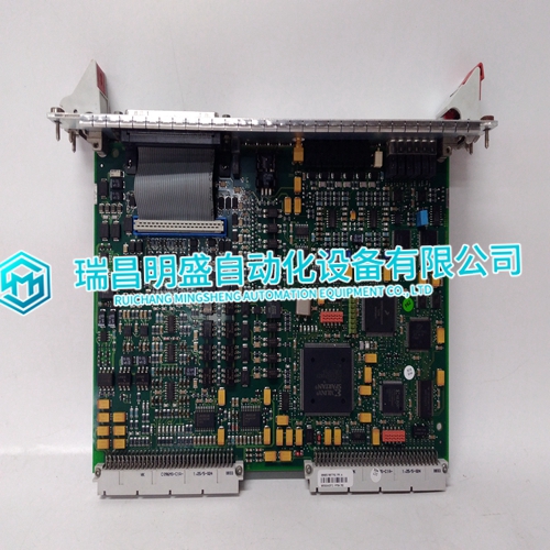
PFSK152 3BSE018877R2 use of the control module size
PFSK152 3BSE018877R2 use of the control module size
Low Output Detection Circuit (PF) Low output voltage detection circuit is provided. Power Fail signal (PF signal) will output when output voltage decrease by either the drop or brown out of the input voltage or OCP, OVP and OTP function operation. PF signal will turn “High” level to indicate the abnormal status of the power supply when the output voltage decrease to 80% of the output voltage setting value. However, there is a possibility that PF signal may not output during parallel operation. The PF signal circuit is insulated from the power supply input and output circuit and it is an open collector. TOG terminal is ground for PF terminal. When the Built-in Fan Motor of this power supply unit stops, PF signal will turn to “H” and the output power will shut down. The Built-in Fan Motor is a component with lifetime. We recommend a periodic replacement. Please contact our sales office. Replacement is at customer’s expenses.
Remote Sensing (+S, -S terminal)
Remote sensing function is provided to compensate for voltage drop across the wiring from the power supply output terminals to the load input terminals. Connect “+S” terminal to “+” terminal of the load and “-S” terminal to “-” terminal of the load with sensing wires. The total line voltage drop (+ side line and - side line) shall be less than 0.3V. In case that sensing line is too long, it is necessary to put an electrolytic capacitor across the load terminals. Please take note that the electrolytic capacitor has generation of heat etc. done by the ripple current depending on connected load. Therefore, the electrolytic capacitor must have a ripple current allowance higher than the output ripple current. If CN01 (or CN02) is in use, terminal +S, -S for CN02 (or CN01) must be in open condition.When the function of remote sensing is not in used, connect +S terminal to +V terminal, and –S terminal to –V terminal by the attachment connector. If remote sensing terminals are opened, the stability and the accuracy of the output deteriorate. Therefore, terminal +S, -S must be connected.
Remote ON/OFF Control
Remote ON/OFF control is provided. Output can be remotely switch ON and OFF by using CNT terminal and TOG terminal even though input is connected. The output is turned to ON when TOG and CNT terminals are shorted and output is turned to OFF when these terminals are opened. When the function is not used, connect TOG and CNT terminals with short piece. The standards for this function are as follows. “TOG” terminal is ground for “CNT” terminal.(1) TTL compatible. The maximum input voltage to CNT terminal is 12V, and the maximum allowable reverse voltage is -1V. The sink current of CNT terminal is 3.5mA. (2) Output ON/OFF control can be enable by a switch, relay or a transistor ON/OFF. When CNT terminal-TOG terminal is shorted power supply is turn ON, and when CNT terminal-TOG terminal is opened power supply is turn OFF. (3) Remote ON/OFF control circuit is isolated from the input and output circuit of power supply. It is possible to use it regardless of the positive and negative of the power supply output.
