Industry news
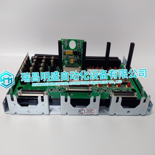
GE GE is used for IS200TVBAH2ACC module
GE GE is used for IS200TVBAH2ACC module
Each I/O Module has a red Fault LED controlled by the CPU, which is turned on when the system is reset. During initialization of an I/O module, which occurs after every CPU reset, the CPU turns the Fault LEDs on. The CPU then tests each I/O module using diagnostic routines built into software. If the diagnostic test is not passed, the LED remains on. If the test is successful, the LED goes off. If the Fault LED on a module is illuminated after the diagnostics and initialization have been run, the module may be faulty or in the wrong slot. LED Diagnostics. If during normal control operation all Kernel I/O modules have their Fault LEDs on, check the Kernel CPU for a failure. If during normal control operation, only one module’s Fault LED is turned on or flashing, replace this module. A flashing LED indicates that a certain module failure has occurred, and is used by factory technicians to locate module faults. When a module fault is detected, its outputs are disabled or de-energized. I/O modules may have a fuse visible at the bottom rear edge of the module. If this fuse is blown, replace it with a fuse of the same type and size.

EXPLOSION HAZARD
Do not connect or disconnect while circuit is live unless area is known to be non-hazardous. Substitution of components may impair suitability for Class I, Division applications. Do not remove or install power supply while circuit is live unless area is known to be non-hazardous. Do not remove or install modules while circuit is energized unless area is known to be non-hazardous.RISQUE D’EXPLOSION—Ne pas raccorder ni débrancher tant que l’installation est sous tension, sauf en cas l’ambiance est décidément non dangereuse. La substitution de composants peut rendre ce matériel inacceptable pour les emplacements de Classe I, applications Division. Ne pas enlever ni installer l’alimentation électrique pendant que le circuit est sous tension avant de s’assurer que la zone est non dangereuse. Ne pas enlever ni installer les cartes pendant que le circuit est sous tension sans s’assurer que la zone non dangereuse.
VME I/O Module Replacement Procedure:
1. Warnings: Read all warnings on pages VI and VII of this Volume before replacing any module. 2. If the control is running and on-line, use the Engineering Workstation to verify that any backup CPU is running without faults. 3. Remove Power: If possible, remove power from the Chassis and continue at step 5. 4. Reset CPU: For simplex CPU systems only: Toggle the CPU switch on a 040 CPU to the reset position. On a MicroNet Plus 5200 CPU or CPU_P1020 system, stop the application using AppManager. (If the CPU reset button is used, be aware that the application will auto-start in approximately 2 minutes.) 5. Remove the cable saddle at the top of the chassis section. The saddle can be lifted off by removing the two screws which hold it in place. 6. Unseat the module: Unscrew the module’s captive-screw fasteners (one at the top of the module and the other at the bottom), and unseat the module by simultaneously pressing the top module handle (extractor) up and the bottom module handle (extractor) down.
The main products
Spare parts spare parts, the DCS control system of PLC system and the robot system spare parts,
Brand advantage: Allen Bradley, BentlyNevada, ABB, Emerson Ovation, Honeywell DCS, Rockwell ICS Triplex, FOXBORO, Schneider PLC, GE Fanuc, Motorola, HIMA, TRICONEX, Prosoft etc. Various kinds of imported industrial parts
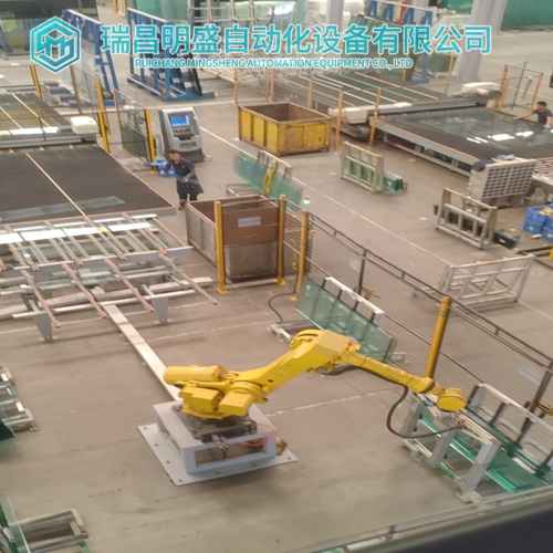
Products are widely used in metallurgy, petroleum, glass, aluminum manufacturing, petrochemical industry, coal mine, papermaking, printing, textile printing and dyeing, machinery, electronics, automobile manufacturing, tobacco, plastics machinery, electric power, water conservancy, water treatment/environmental protection, municipal engineering, boiler heating, energy, power transmission and distribution and so on.

