Industry news
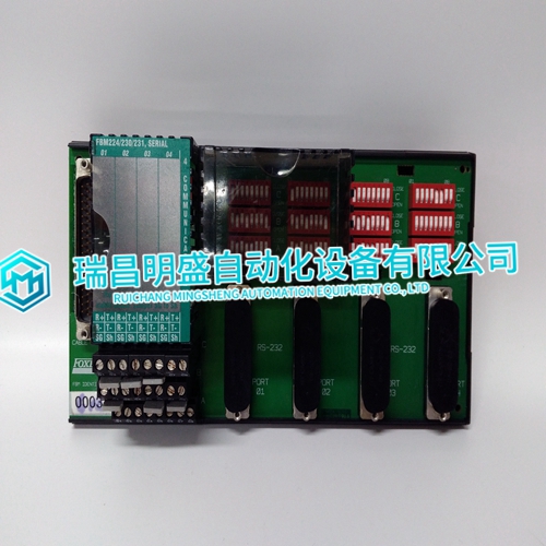
FOXBORO P0926GH series I/O products
FOXBORO P0926GH series I/O products
Partially remove the module and disconnect cables: Pull the module straight out along the card guide slots until it is approximately 25 mm (1 inch) from the motherboard. Disconnect the I/O cables from the module, and secure the ends to avoid damage or shorting of pins. The I/O cables use a slide latch (to disengage, slide the latch towards the top of the module). 8. Fully remove the module: Remove the module by pulling it straight out and putting it into a conductive plastic bag. (Woodward P/N 4951-041). 9. Inspect and partially install module: Prior to installing a replacement module, verify that all connector pins are parallel and straight. Install the replacement module by aligning the circuit board edges inside the card guides and pushing the module straight in until it is approximately 25 mm (1 inch) from the motherboard. (Do not make contact with the chassis motherboard mating connectors.) 10. Delay time: If the same module is to be removed and re-installed, wait a minimum of 30 seconds after removal before re-installing the module 11. Re-connect the cables: Connect the I/O cables to the module. The I/O cables use a slide latch (to engage, slide the latch towards the bottom of the module). Verify that the I/O cables are connected to the correct cable connector. Re-position the two captive-screw fasteners as necessary to prevent interference when the module is inserted.
Fully insert the I/O module
With even pressure exerted at the top and the bottom of the module, in one continuous motion, fully seat the module into the motherboard. If resistance is encountered when installing a module, do not force the module. Remove the module and check the connectors for bent contacts or foreign objects. Also check to ensure that the module screws are fully retracted. Forcing a module into place may break the connector or bend the securing screws. 13. Tighten the two captive-screw fasteners (one at the top of the module and the other at the bottom). 14. If power was removed, reapply power. 15. Put a 040 CPU module back in run mode by toggling the CPU switch.16. On the MicroNet Plus 5200 CPU or CPU_P1020 system, re-start the application as required using AppManager 17. Verify that the replacement MicroNet module is working correctly. 18. Reinstall the cable saddle. Once the module is properly installed, the module Fault LED will be illuminated until the module is re-initialized by the control. The control performs module diagnostic tests for a few seconds, and if all tests are passed, re-initializes the module (turning off the module Fault LED).
eplacing a Field Termination Module
Toggle the CPU switch to the reset position. 2. Carefully—to avoid shorting cable pins—disconnect all I/O cables from the FTM, and secure cable ends to avoid damage or shorting of pins. The I/O cables use a slide latch (to disengage, slide the latch to the release position). 3. Disconnect all field wiring. Care should be taken to avoid shorting the wires. 4. Remove the FTM by inserting a screwdriver into the mounting foot and prying each foot away from the DIN rail. Install the replacement FTM. 5. Reconnect all field wiring. Refer to the Wiring Notes for the appropriate module. 6. Connect all I/O cables to the FTM, being careful to avoid shorting cable pins. Lock the connector in position by sliding the latch to the latched position. 7. If power was removed, reapply power. 8. Put the CPU module back in run mode. 9. Verify that the new FTM is working correctly.It is not possible to replace an FTM without shutting down the entire control system and the prime mover.
If power has not been removed from the control system, power will be active at the module and also at the cable connectors. It is recommended that the cables not be removed until after the module has been unseated. If cables are removed with power applied, care must be used to avoid shorting cable connector pins. HIGH VOLTAGE—If the high voltage FTM is being used with the 48/24 Discrete I/O module, and there is 125 Vdc on the FTM terminal blocks, there will be 125 Vdc on the FTM sub D connectors and on the cable when it is connected to the FTM. For this reason, all power should be removed from the FTM terminal blocks before disconnecting any cables.
The main products
Spare parts spare parts, the DCS control system of PLC system and the robot system spare parts,
Brand advantage: Allen Bradley, BentlyNevada, ABB, Emerson Ovation, Honeywell DCS, Rockwell ICS Triplex, FOXBORO, Schneider PLC, GE Fanuc, Motorola, HIMA, TRICONEX, Prosoft etc. Various kinds of imported industrial parts
Products are widely used in metallurgy, petroleum, glass, aluminum manufacturing, petrochemical industry, coal mine, papermaking, printing, textile printing and dyeing, machinery, electronics, automobile manufacturing, tobacco, plastics machinery, electric power, water conservancy, water treatment/environmental protection, municipal engineering, boiler heating, energy, power transmission and distribution and so on.