Industry news
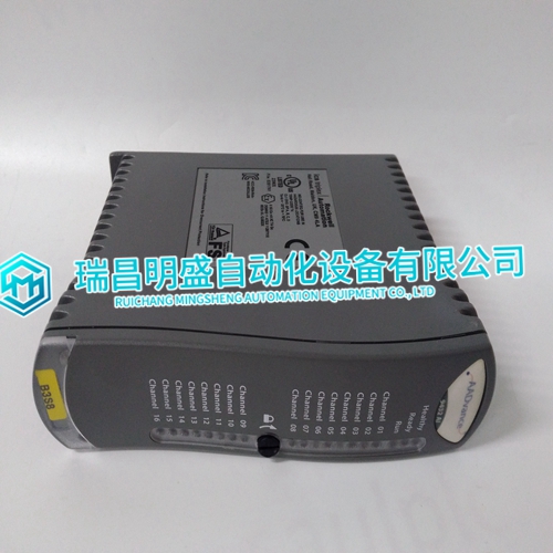
ICS TRIPLEX T9432 application of PLC controller
ICS TRIPLEX T9432 application of PLC controller
A contact to override the failed-speed-signal circuit can be installed in series with terminal 18 and the dc power to the control. When the contact is open, the control operates normally, turning the control output off in the event of a loss of speed signal. Closing the contact overrides the failed-speed-signal circuit as may be required for start-up. Prior to start-up of the prime mover, the speed signal is nonexistent. On prime movers with cranking motors, the cranking speed is usually sufficient to provide a speed signal, so an override contact on terminal 18 is not needed for starting. On some steam turbine systems, the Close to Override Failed Speed Signal contact must be closed in order to allow the actuator to open and provide steam for starting. If a failed-speed-signal-override contact is used, it should be of the momentary type to ensure that the failed-speed-sensor shutdown circuit is enabled after start-up.
Idle/Rated Ramp Contact
Connect a single-pole, single-throw contact from terminal 16 (terminal 0 on highvoltage controls) to terminal 19, the Close For Rated (open for idle, close for rated) terminal. Oil pressure is often used to close this contact. When closed, 20 to 40 Vdc is applied to terminal 19, and the prime mover can be operated at a speed higher than idle. When the contact is open, the voltage is removed from terminal 19, and the prime mover’s speed immediately decelerates to idle.

Actuator Output
The actuator wires connect to terminals 20 (+) and 21 (–). Use shielded wires with the shield connected to terminal 22. Do not connect the shield to the actuator or any other point. The shield must have continuity the entire distance to the actuator, and must be insulated from all other conducting surfaces. Refer to the manuals listed in Chapter 1, References, table for additional information on actuator installation.
External Speed Trim
A jumper must be connected to terminals 23 and 24 unless an optional remote Speed Trim potentiometer is used. If a Speed Trim potentiometer is used. connect it as shown in the plant wiring diagram (Figure 1-2), using shielded wire. Connect the shield to terminal 22. Make sure the shield has continuity the entire distance to the potentiometer, and that the shield is insulated from all other conducting surfaces. A 100 Ω potentiometer will provide ±5% speed adjustment. If less adjustment is desired, potentiometers of smaller values may be used. Potentiometers of the multi-turn type are recommended
The main products
Spare parts spare parts, the DCS control system of PLC system and the robot system spare parts,
Brand advantage: Allen Bradley, BentlyNevada, ABB, Emerson Ovation, Honeywell DCS, Rockwell ICS Triplex, FOXBORO, Schneider PLC, GE Fanuc, Motorola, HIMA, TRICONEX, Prosoft etc. Various kinds of imported industrial parts
Products are widely used in metallurgy, petroleum, glass, aluminum manufacturing, petrochemical industry, coal mine, papermaking, printing, textile printing and dyeing, mechanical, electronic manufacturing, automobile manufacturing, plastic machinery, electric power, water