Industry news
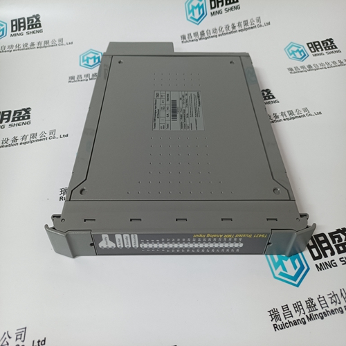
ICS TRIPLEX T8431 Digital module USES tutorial
ICS TRIPLEX T8431 Digital module USES tutorial
Speed and Phase Matching (SPM) Synchronizer Connect the SPM Synchronizer (optional equipment) wires to terminals 25 (+) and 26 (–). Use shielded wire, and connect the shield to terminal 27. Make sure the shield has continuity the entire distance to the SPM Synchronizer, but do not connect the shield to the synchronizer. The shield must be insulated from all other conducting surfaces.
Connect a speed-sensing device, such as a magnetic pickup, to terminals 28 and 29 using shielded wire. Connect the shield to terminal 27. making sure the shield has continuity the entire distance to the speed sensor, and that the shield is insulated from all other conducting surfaces.
The actuator lever should be near but not at the minimum position when the fuel or steam rack is at the minimum position. If the actuator lever gets to its minimum position before completely shutting off fuel or steam, the control may not be able to shut the turbine down, causing damage to equipment or injury or death.
ACTUATOR COMPENSATION. A. Set the ACTUATOR COMPENSATION potentiometer at 2 on the 0 to 10 potentiometer scale for diesel, gas turbine, or fuel-injected gasoline prime movers. B. Set the ACTUATOR COMPENSATION potentiometer at 6 on the 0 to 10 potentiometer scale for carbureted-gas or gasoline prime movers, and steam turbines.
Installation Check-out Procedure
With the installation completed as described in this chapter, do the following check-out procedure before beginning the start-up adjustments in Chapter 3. 1. Visual Inspection A. Check the linkage between the actuator and the prime mover for looseness or binding. Refer to the appropriate actuator manual and to Woodward manual 25070, Electronic Governor Installation Guide, for additional information on linkage.B. Check for correct wiring per the plant wiring diagram (Figure 1-2). C. Check for broken terminals and loose terminal screws. D. Check the speed sensor for visible damage. If the sensor is a magnetic pickup, check the clearance between the gear and the sensor, and adjust if necessary. Clearance should be between 0.25 and 1.00 mm (0.010 and 0.040 inch) at the closest point. Make sure the gear has less than 0.50 mm (0.020 inch) diametric runout. See Woodward manual 82510, Magnetic Pickups & Proximity Switches for Electronic Governors.
Check for GroundsMake sure power is off. Check for grounds by measuring the resistance from terminal 11 to chassis, and from terminal 15 to 11. The resistance should be infinite. If a resistance other than infinite is obtained, remove the connections from each terminal one at a time until the resistance is infinite. Check the line that was removed last to locate the fault.
The main products
Spare parts spare parts, the DCS control system of PLC system and the robot system spare parts,
Brand advantage: Allen Bradley, BentlyNevada, ABB, Emerson Ovation, Honeywell DCS, Rockwell ICS Triplex, FOXBORO, Schneider PLC, GE Fanuc, Motorola, HIMA, TRICONEX, Prosoft etc. Various kinds of imported industrial parts
Products are widely used in metallurgy, petroleum, glass, aluminum manufacturing, petrochemical industry, coal mine, papermaking, printing, textile printing and dyeing, mechanical, electronic manufacturing, automobile manufacturing, plastic machinery, electric power, water