Industry news
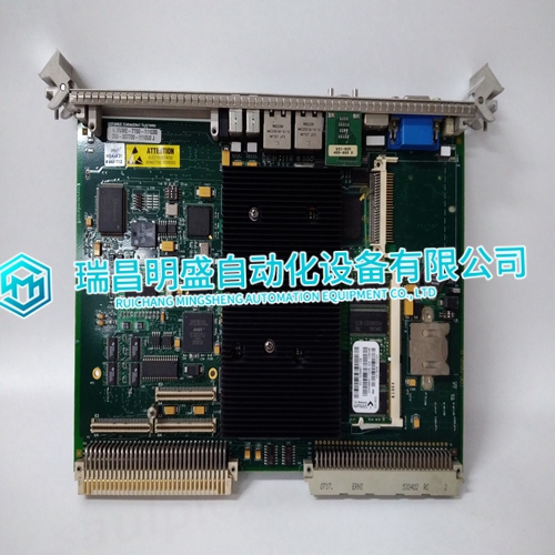
VMIVME-7700-111000 Ge instructions
VMIVME-7700-111000 Ge instructions
Speed Sensor Check If the sensor is a magnetic pickup, measure the voltage across terminals 28 and 29 to be sure there is a minimum of 1.0 V at cranking speed, and a maximum of 30 Vrms at rated speed. If the voltage exceeds 30 V, increase the gap of the speed sensor, and be sure that there is still a minimum of 1.0 V at cranking speed.1. Connect a dc voltmeter to control terminals 11 (–) and 13 (+) to measure the load signal. 2. Start the prime mover. With the generator operating in the isochronous mode and not paralleled, load the generator to as near to full load as possible. Measure the load-signal voltage. 3. Unload and shut down the prime mover. Disconnect the wire from terminal 5, and connect both wires from phase A CT to terminal 4.4. Start the prime mover, apply full load (or the same load as obtained in step 2) and again measure the load signal at terminals 11 and 13. If the load signal voltage is not 1/3 lower than the reading obtained in step 2, the phasing is incorrect. Unload and shut down the prime mover. Reconnect phase A CT wire from terminal 4 to terminal 5, maintaining the original polarity. If the phasing is incorrect, proceed to the Phase Correction Procedure. If the phasing appears correct, skip the Phase Correction Procedure and go to the Load Gain Adjustment procedure.

Phase Correction Procedure
The highest positive voltage will be obtained when the CTs are correctly matched to the load-sensor terminals in both phase and polarity. The following procedure will assure the correct connection of the current transformers. It is required only if the phasing check indicates incorrect phasing, or loading stability is extremely sensitive to the power factor. Trial connections of the first CT to all three load-sensor inputs, polarized both ways, are made (a total of six connections). The load-signal voltage is recorded for each connection and the first CT is then connected to the terminals that produce the highest positive voltage, and with the polarity that produces the highest positive voltage.
The Phase Correction Procedure requires
that the prime mover be shut down many times to disconnect the current transformers. For convenience, a temporary method of connecting the current transformers shown in Figure 3-2 is recommended. Connecting a 1 Ω, 5 W burden resistor across each current transformer allows the current transformers to be disconnected from the terminal strip with the prime mover running, after removing all load. The second CT is tried on each of the remaining two CT input terminals, in each polarity, and the voltage recorded. The second CT is then connected to the terminals that produce (and with the polarity that produces) the highest positive voltage. The last CT is then tried on the remaining input terminals, polarized both ways, and the voltage recorded. Connecting the last CT in the polarity that produces the highest voltage completes the procedure
The main products
Spare parts spare parts, the DCS control system of PLC system and the robot system spare parts,
Brand advantage: Allen Bradley, BentlyNevada, ABB, Emerson Ovation, Honeywell DCS, Rockwell ICS Triplex, FOXBORO, Schneider PLC, GE Fanuc, Motorola, HIMA, TRICONEX, Prosoft etc. Various kinds of imported industrial parts
Products are widely used in metallurgy, petroleum, glass, aluminum manufacturing, petrochemical industry, coal mine, papermaking, printing, textile printing and dyeing, mechanical, electronic manufacturing, automobile manufacturing, plastic machinery, electric power, water