Industry news
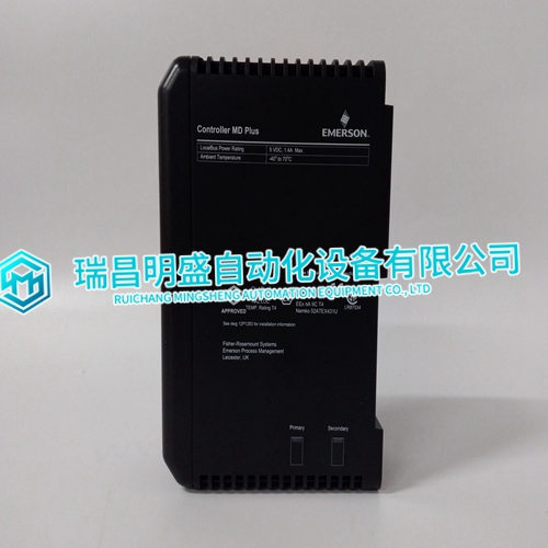
VE3006 12P3439X012 G6450081A KJ2003X1-BB1 Module size
VE3006 12P3439X012 G6450081A KJ2003X1-BB1 Module size
If the temporary burden resistors described above and shown in Figure 3-2 are not used, the prime mover MUST be shut down in addition to removing the load in the following procedure. Measure the load-signal voltage in this procedure by connecting a voltmeter across the Load Signal terminals 11 (–) and 13 (+). 1. Shut down the prime mover. 2. Label each CT wire with the phase and polarity that you think it should be. Even though this identification may prove to be incorrect, this step is necessary so that the individual wires may be identified during the description of the procedure. 3. Disconnect the phase B CT wires from terminals 6 and 7. Connect these two wires together using a small screw and nut, and tape the connection. 4. Disconnect the phase C CT wires from terminals 8 and 9. Connect and tape these two wires together as in step 3. 5. Connect the two wires from the phase A CT to the phase A input terminals 4 and 5. 6. Start the prime mover, apply full load, and measure the load signal voltage. Start a list and record this voltage.
Unload the system and reverse the phase A CT wires on terminals 4 and 5. * 8. Apply full load, measure the load signal, and record this voltage. 9. Unload the system, remove the phase A CT wires from terminals 4 and 5, and connect them to phase B input terminals 6 and 7. * 10. Apply full load, measure the load signal, and record this voltage. 11. Unload the system and reverse the phase A CT wires on terminals 6 and 7. * 12. Apply full load, measure the load signal, and record this voltage. 13. Unload the system, remove the phase A CT wires from terminals 6 and 7, and connect them to phase C input terminals 8 and 9. * 14. Apply full load, measure the load signal, and record this voltage.
Load Gain Adjustment
For this procedure, the generator must be running isochronously and not paralleled. Connect a dc voltmeter across terminals 11 (–) and 13 (+) to measure the load-signal voltage. Start the prime mover and apply full load. Measure the load signal voltage and adjust the LOAD GAIN potentiometer for 6.0 V. * If full load is not obtainable, decrease the LOAD GAIN proportionally to the load. For example, at 50% load adjust the LOAD GAIN to 3 V. When paralleled in the isochronous mode or on an isolated bus, generator speeds must be the same. If they are not equal, load sharing will not remain proportional as the load varies. Any difference in loads between the units can be corrected by adjusting the Load Gain Potentiometer. Increasing the LOAD GAIN (turning the potentiometer clockwise) will cause that generator to carry less load. If stability problems occur when paralleled at a particular load-signal voltage, reduce the voltage by reducing the LOAD GAIN (turn the potentiometer counterclockwise), and reduce the load-signal voltage setting of all other generators in the system to the same voltage. When the load-signal voltages of all generators in a system are reduced, the load-sharing gain will be reduced, and this may result in some loss of load-sharing sensitivity.
The main products
Spare parts spare parts, the DCS control system of PLC system and the robot system spare parts,
Brand advantage: Allen Bradley, BentlyNevada, ABB, Emerson Ovation, Honeywell DCS, Rockwell ICS Triplex, FOXBORO, Schneider PLC, GE Fanuc, Motorola, HIMA, TRICONEX, Prosoft etc. Various kinds of imported industrial parts
Products are widely used in metallurgy, petroleum, glass, aluminum manufacturing, petrochemical industry, coal mine, papermaking, printing, textile printing and dyeing, mechanical, electronic manufacturing, automobile manufacturing, plastic machinery, electric power, water