Industry news
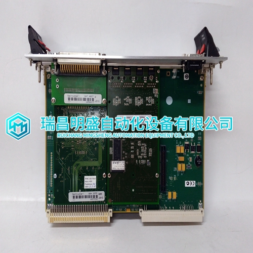
MVME6100 Interface module using the tutorial
MVME6100 Interface module using the tutorial
Transmitters powered from the Single Channel Control Card require either three or four wire connections and the sensor documentation will indicate the 0V and +24V power connections and the positive and negative loop connections. At the System 57 end of the field cable the sensor wires should be connected to the S, 01, NS, 0V or 24V terminals on the Field Interface or Relay Card that is attached to the required Single Channel Display Card. The exact terminals used vary depending upon whether three or four wire topology is used, and the requirement for loop current source or sink configuration. Link options must also be set correctly on the 4- 20mA Sensor Drive Module (see Section 12.3). The sensor cable screen should be connected to the system earth at the Field Interface/Relay Card, using the GROUND terminal, or where the cable enters the cabinet using a metal cable gland, or by other suitable means.

Note:
Where a sensor is earthed locally, either to the Earth Stud or through the sensor casing or mounting, to avoid earth loops the screen sheath of the cable should only be connected at one end. ie. At the sensor or at the Interface/relay Card. 2. The Optima analogue output is non isolated and is factory configured as current sink or current source. The actual configuration is identified by a label on the Optima white 4 - 20mA output lead Single Channel Control Card 4 - 20mA 05701-A-0301 Fitted with 4 - 20mA Sensor Drive 05701-A-0283 The Searchline Excel Cross Duct analogue output is non isolated and is factory configured as current sink or current source. Connector and link settings are shown for current source model only, contact Zellweger Analytics for other option.
OUTPUT CONNECTIONS
14.1 Relay Outputs Note: 1. The FAULT relay is permanently configured for normally ENERGISED operation in the non-fault condition. 2. Unless the High Integrity Relay Card is fitted, the INHIBIT relay (where fitted) is permanently configured for normally DE-ENERGISED operation in the non-inhibit condition. 3. The Alarm relays may be configured for either normally energised or normally de-energised operation. Refer to the configuration printout or use the relays screen of the Engineering Interface Software to determine the configuration.There are four relay card types providing different levels of alarm relay capability (See Chapter 2 Section 5). The cabling to the relays should where possible be kept away from the sensor cabling, especially those cables carrying mains supplies. The following figure shows the relay contact connections as shown on the terminal block.
THE Main products
PLC programmable controller module, DCS card, ESD system card, vibration monitoring system card, steam turbine control system module, gas generator spare parts, etc. Advantage brands: Allen Bradley, BentlyNevada, ABB, Emerson Overseas, Honeywell DCS, Rockwell ICS Triplex, FOXBORO, Schneider PLC, GE Fanuc, Motorola, HIMA, TRICONEX, Prosoft and other imported industrial parts
The products are widely used in metallurgy, oil and gas, glass manufacturing, aluminum, petrochemical, coal mine, paper and printing, textile printing, machinery, electronic manufacturing, automobile manufacturing, plastic machinery, power, water conservancy, water treatment/environmental protection, boiler heating, energy, power transmission and distribution, etc
