Industry news
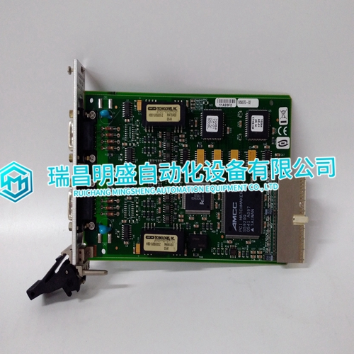
NI PXI-8423 Output module parameters
NI PXI-8423 Output module parameters
The following guide to commissioning and maintenance should be used in conjunction with the relevant instructions issued with the sensors being used. The following information applies to the setup of a system with a single power supply connection to the DC Input Card. For information on systems where power is applied to each individual channel, please contact Zellweger Analytics.
Check the operation of the connected sensor by checking the BEAD mA and mV SIGNAL for a catalytic sensor or the mA SIGNAL for a 4 - 20mA sensor.Repeat Steps (11) to (14) for the remaining control cards in the rack.) Reconnect the terminal block TB2 to the DC Input Card and test the optional Engineering Card module in accordance with the relevant operating manual instructions.Verify the alarm configuration for each channel using the relay test procedure outlined in Chapter 7 Section 6.Verify that the System 57 Control Cards and power supply are operating within the maximum specified operating temperature of 55 C.
START UP PROCEDURE
A detailed check of the system wiring should be carried out prior to this start-up procedure. Start-up the system as follows: (1) Ensure that the system power supply is switched off. (2) Disconnect the power supply connections to the DC Input Card by removing the two part connector TB1. Remove terminal block TB2 if used. (3) Unscrew the two retaining screws used to secure the control cards and then, using the extraction tool, partially remove the cards from the rack so that there is no electrical connection between the control cards and the backplane. (4) Switch on the system power supply. (5) Check that a voltage of between 18V and 32V dc exists at the terminal block TB1.
Switch off the power supply.
(7) Reconnect the terminal block TB1 to the DC Input Card. (8) Switch on the system power supply. (9) Check that a voltage of between 18V and 32V dc still exists at the terminal block TB1. (10) Check that the Engineering Card front panel power on ( ) green LED is illuminated and the unlocked ( ) LED is flashing. (11) Push the control card in slot 1 fully into the rack so that it makes connection with the backplane and secure with the two securing screws. (12) Check that the display operates and that the INHIBIT LED on the control card front panel is illuminated. (13) Check that after the pre-defined start up inhibit period, typically 30 seconds, the INHIBIT LED is extinguished.
THE Main products
PLC programmable controller module, DCS card, ESD system card, vibration monitoring system card, steam turbine control system module, gas generator spare parts, etc. Advantage brands: Allen Bradley, BentlyNevada, ABB, Emerson Overseas, Honeywell DCS, Rockwell ICS Triplex, FOXBORO, Schneider PLC, GE Fanuc, Motorola, HIMA, TRICONEX, Prosoft and other imported industrial parts
The products are widely used in metallurgy, oil and gas, glass manufacturing, aluminum, petrochemical, coal mine, paper and printing, textile printing, machinery, electronic manufacturing, automobile manufacturing, plastic machinery, power, water conservancy, water treatment/environmental protection, boiler heating, energy, power transmission and distribution, etc