Industry news
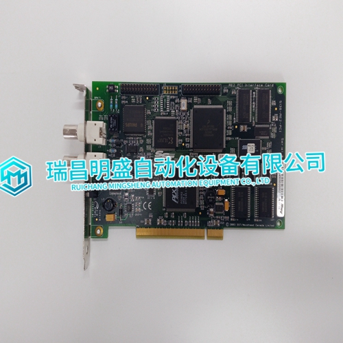
5136-RE2-PCI applied to SST interface module
5136-RE2-PCI applied to SST interface module
Module Repair and Replacement If the ASI module is faulty, replace it with a new one. Do not try to repair the module; replacing components may affect the module performance. Modules can be removed while system power is supplied. To replace a module: 1. Push and turn the two front panel captive latches one half turn to unlatch the module. It is unlatched when the slots on the latches are vertical and the open end of the slots face away from the center of the module. 2. Gently slide the module out of the module mounting unit (MMU). 3. Configure the replacement module switch and jumper settings. Ensure they are set the same as the original module. 4. In the same slot assignment as the original module, align the replacement module with the guide rails in the module mounting unit. Gently slide it in until the front panel is flush with the top and bottom of the MMU frame. 5. Push and turn the two captive latches on the module faceplate one half turn to the latched position. It is latched when the slots on the latches are vertical and the open ends face the center of the module. 6. Return to normal operation

Introduction
The IMASI13 module (ASI) uses one NTAI06 termination unit for termination. Jumpers on the termination unit configure each of the 16 analog inputs for either system powered 4 to 20 milliamperes, external powered 4 to 20 milliamperes, three-wire RTD, differential voltage, or single-ended voltage. NTAI06 termination units with both revision A and revision B hardware are in service. This section contains information on revision A and B units (refer to Figure A-1 and A-2).
Cold Junction Reference Input
Each NTAI06 termination unit has a pair of RTDs which measure the temperature of the termination unit. This temperature is used to compensate for the cold junction effect on thermocouple inputs. When using the built-in cold junction reference, the termination unit covers should be in place. The cover encloses both the terminal blocks and the RTD. It helps maintain the same temperature around the terminal blocks and the RTD. Maintaining both at the same temperature allows maximum accuracy for thermocouple inputs. To apply the built-in cold junction reference for thermocouple inputs, refer to function code 215 specifications and block outputs in the Function Code Application Manual.
