Industry news
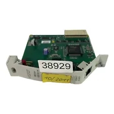
EI803F 3BDH000017R1 Applicable to analog communication card
EI803F 3BDH000017R1 Applicable to analog communication card
This jumper configuration connects the plus (+) and minus (-) inputs and the COM input directly to IMASI13 three-wire input. Channel to channel and channel to system signal isolation is maintained. The two common leads of the RTD element should be connected across the plus (+) and common (C) terminals, and the third lead should be connected to the minus (-) terminal.
Figure A-7 shows the jumper connection when using an IMASI13 module with firmware B.0 or higher and four pin jumper blocks (J1 - J16). This special connection is required for the millivolt and RTD input.

Replacing an IMASI03 Module
There are two differences between the IMASI03 module and the IMASI13 module, resolution/scan time and power consumption. Once these two factors are taken into consideration, the IMASI13 module can be used as a direct replacement for the IMASI03 module. The IMASI03 module resolution for the analog to digital conversion for each independent channel can be set at 16, 18, 20, 22, and 24. For the IMASI13 module, the resolution for each channel is 24 bits only
Function Code 216 Modifications
Two changes are required to function code 216 when replacing an IMASI03 module with an IMASI13 module. 1. Change specification S4 from x40 to x44 if the input channel is configured for a 1 to 5 VDC. 2. Change specification S11 to 24 bit A/D conversion resolution. NOTE: If 16, 18, 20, or 22 bits resolution is already selected in function code 216, the IMASI13 module will automatically default to the 24 bit resolution. This change is only necessary to insure the specifications accurately reflect the module capabilities. Refer to Table 1-4 for typical analog to digital conversion rates. The rate specified is the conversion time for all channels.
