Industry news
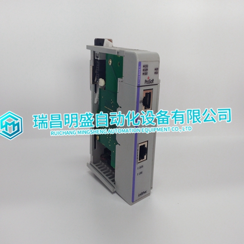
PROSOFT MVI69-MNET Configuration steps of communication module
PROSOFT MVI69-MNET Configuration steps of communication module
In most instances, this small difference in power consumption will not require any changes to the power supplies. To insure this, be certain to check all of your calculations for power supply sizing and system current requirements and adjust as necessary for the IMASI13 power consumption specification.Inputs can be used for count signals, direction, disable, edgesensitive strobe, and other inputs. Outputs can be used to drive indicating lights, solenoids, relays, and other devices. Each output has a response delay of 1ms maximum; repeatability is 0.5ms or less. Each output circuit provides built-in protection against power surges caused by wiring errors. The block also provides a +5 volt DC output and a CMOS/TTLcompatible oscillator output. The block’s Counts Per Timebase register indicates the number of counts in a programmable time interval. For each counter, this is a 16-bit signed number. The sign indicates net up counts (+) or down counts (-) in the time period.

The block may be powered by 115 VAC or 10 to 30 VDC.
Auxiliary DC power can be used when the main power to the block is supplied by 115 VAC. Both 115 VAC and DC power may be supplied simultaneously and if the 115 VAC source fails, the block will continue to operate on the DC backup power. Any DC source that can provide an output in the range of 10 VDC to 30 VDC can be used. The source must meet the specifications listed in the table on page 1 of this datasheet. With both AC and DC power applied, block power will be taken from the AC input as long as the DC voltage is less than 20 volts
Each output has a response delay of 1ms maximum;
repeatability is 0.5ms or less. The commanded state of each output is shown by an individual LED on the block. Outputs may be forced on or off using the Hand-held Monitor, or by command from the application program. This is useful during installation and checkout. Each output has built-in electronic protection against short circuits. If an output is commanded to turn on and the current through the switch exceeds 4 Amps for a period of 1 millisecond, the block automatically shuts off the switch and generates a FAILED SWITCH diagnostic. Short circuit protection protects the block if loads are 4 Amps or more. Each output on the block can source a maximum of 0.5 Amps. Switching of loads between 0.5 Amps and 4 Amps is shown below.
