Industry news
1X00416H01 WH5-2FF OVATION system power supply module
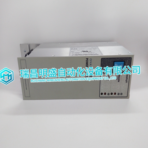
1X00416H01 WH5-2FF OVATION system power supply module
Block Mounting Genius I/O blocks are considered "open equipment" and therefore must be installed within a protective enclosure. They should be located in an area that is clean and free of airborne contaminants. There should be adequate cooling airflow. The block can be mounted right side up, or upside down. Leave at least 2 inches of space between blocks. Mount the block by drilling two screw or bolt holes for 8-32 hardware. Position the block so that the notches in the upper and lower flanges line up with the mounting holes. Mount the block using 8-32 screws. Use star washers to provide ground integrity. Grounding The block’s mounting screws must not be used as the only means of grounding the block. Connect the green ground screw on the block to a reliable ground system using a short wire lead, minimum size AWG #12 (avg 3.3mm2 in cross-section).
Inserting an Electronics Assembly
1. Align the Electronics Assembly in the guides and push down firmly. Caution Do not exert excessive force; it may damage the block. 2. If unusual resistance is met, remove the Electronics Assembly. If power is applied to the block, DO NOT TOUCH THE CONNECTOR PINS! Inspect the Terminal Assembly, connector receptacle, and connector edge board (on the Electronics Assembly). Be sure the keying matches. Remove any obstacles and reinsert the Electronics Assembly. Pay close attention to the alignment of the guide pins. 3. Secure the Electronics Assembly with the screws on the top and bottom of the Terminal Assembly. Note: If the Electronics Assembly has been removed from a block for some length of time, contaminants may have built up on the exposed connector pins. After the block is reassembled, these contaminants could affect the accuracy of measurements. When reassembling the block, push the Electronics Assembly in and out a few times to assure a fresh mating surface
Serial Bus Wiring
Terminals 1 to 4 are for the serial bus. These terminals accept one AWG #12 wire (avg 3.3mm2 cross-section) or two AWG #14 wires (each avg 2.1mm2 in cross-section). The minimum recommended wire size is AWG #22 (avg .36mm2 in cross-section). Terminals 1 - 4 can also accommodate spade or ring terminals up to 0.27 inch (6.85mm) wide with a minimum opening for a #6 screw, and up to 0.20 inch (5.1mm) depth from the screw center to the back barrier. Be sure unshielded wire ends are not longer than 2 inches (5 cm). Using one of the cable types recommended in the System and Communications User’s Manual, connect the serial bus to terminals 1- 4.
