Home > Product > DCS control system > REF615A_E HAFAABAAABE1BCA1XE +R474A11XE control panel
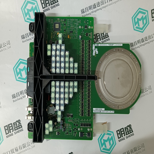
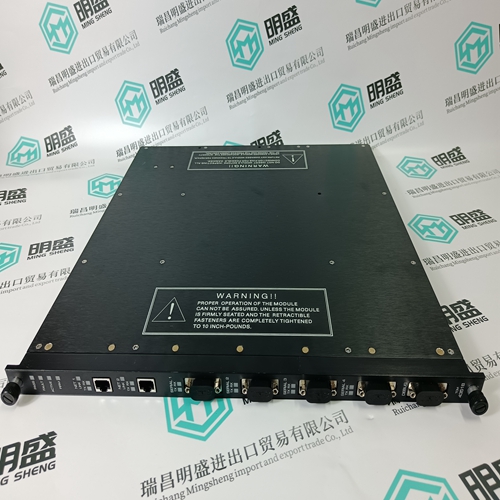
REF615A_E HAFAABAAABE1BCA1XE +R474A11XE control panel
- Product ID: REF615A_E HAFAABAAABE1BCA1XE +R474A11XE
- Brand: ABB
- Place of origin: The Swiss
- Goods status: new/used
- Delivery date: stock
- The quality assurance period: 365 days
- Phone/WhatsApp/WeChat:+86 15270269218
- Email:stodcdcs@gmail.com
- Tags:REF615A_E HAFAABAAABE1BCA1XE +R474A11XEcontrol panel
- Get the latest price:Click to consult
The main products
Spare parts spare parts, the DCS control system of PLC system and the robot system spare parts,Brand advantage: Allen Bradley, BentlyNevada, ABB, Emerson Ovation, Honeywell DCS, Rockwell ICS Triplex, FOXBORO, Schneider PLC, GE Fanuc, Motorola, HIMA, TRICONEX, Prosoft etc. Various kinds of imported industrial parts
Products are widely used in metallurgy, petroleum, glass, aluminum manufacturing, petrochemical industry, coal mine, papermaking, printing, textile printing and dyeing, machinery, electronics, automobile manufacturing, tobacco, plastics machinery, electric power, water conservancy, water treatment/environmental protection, municipal engineering, boiler heating, energy, power transmission and distribution and so on.

REF615A_E HAFAABAAABE1BCA1XE +R474A11XE control panel
For the unregulated 5 kW and 10 kW infeed modules, the commutating reactor is integrated. With 28 kW, it must be external. For connection of the regulated infeed/regenerative feedback modules to the line supply, the HF/HFD reactor tuned to 7 kHz is required (see selection Table 6-12). The HFD reactors perform the following functions: To limit the harmonics fed back into the line supply Energy store for the step–up operation of the infeed units Current limiting for line supply oscillations Together with a damping resistor, the HFD reactors dampen the system oscillations of the converter system. The HF reactors are replaced with the HFD reactors with damping resistor because they provide increased operational reliability and a longer lifetime. The HFD reactor should be mounted as close as possible to the line supply infeed module. ! Caution The surface of the reactors can reach high temperatures. The 100 mm clearance above and below the components to ensure air circulation and cooling must be carefully maintained. If this is not observed, then the components could prematurely age. Temperature–sensitive components must be located a sufficient distance away or thermally partitioned off!
The connecting cables
to the NE module must be kept as short as possible (max. 5 m). For lengths exceeding 1 m, twisted shielded connection lines, with the shielding contacting ground on both side, should be used. It is preferable that the cable shield is connected close to the reactor footplate, using a clamp that completely encompasses the shield Notice It is not permissible to use HFD reactors in the motor cable. Operation without a damping resistor is not permissible, as high voltages (several kV) can occur if the system oscillates Note If commutating reactors are used that have not been released by SIEMENS for SIMODRIVE 6SN11, harmonics or switching edges not permitted for the semiconductors can occur that can damage, disturb or early age other equipment connected to the particular line supply
Integration into the overall system
The monitoring module contains an electronic power supply and central monitoring functions, which are required to operate the drive modules.Reader’s note For an overview of the interfaces, refer to Section 6.2.1, Table 6-1 in the column ”Terminals used” under monitoring module. For operation of the monitoring module only on the DC link, without AC power supply, 1000 μF per monitoring module must be observed for the loading limit of the line supply. This capacity is not included in the calculation of the permitted number of pulsed resistors, because they are de–coupled using diodes.If these parameters are in the permissible operating range, then the internal prerequisites for the ”Unit ready” signal are available. The module group connected to the monitoring module is enabled as soon as the external enable signals have been issued via terminals 63 (pulse enable) and 64 (drive enable). The total signal activates the ”Ready” relay and can be fetched potential–free using the 74/73.2 and 73.1/72 terminals. The load capability of the contacts is 250 V AC/1 A or 30 V DC/1 A. LEDs on the front panel of the monitoring module indicate the signal states of the monitoring circuits.