Home > Product > DCS control system > 1C31179G01 Output module
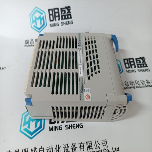
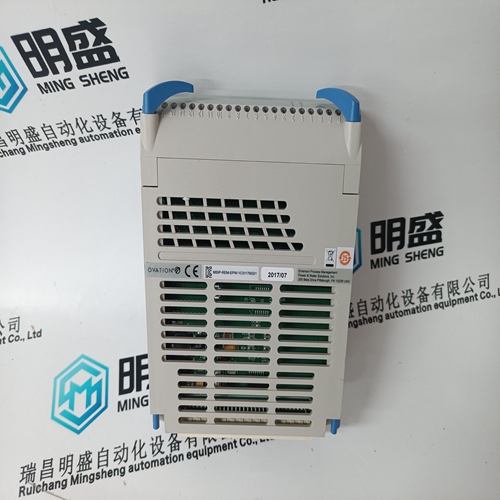
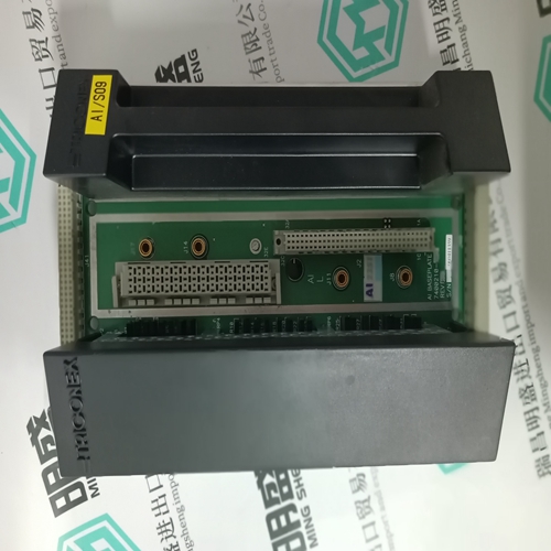
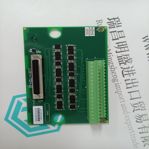
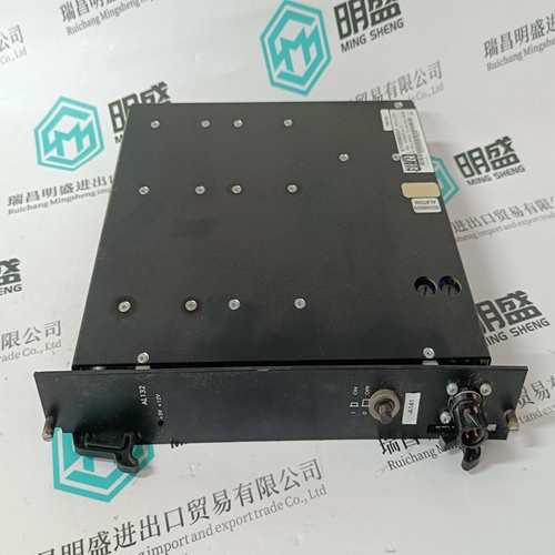
1C31179G01 Output module
- Product ID: 1C31179G01
- Brand: EMERSON
- Place of origin: The United States
- Goods status: new/used
- Delivery date: stock
- The quality assurance period: 365 days
- Phone/WhatsApp/WeChat:+86 15270269218
- Email:stodcdcs@gmail.com
- Tags:1C31179G01Output module
- Get the latest price:Click to consult
The main products
Spare parts spare parts, the DCS control system of PLC system and the robot system spare parts,Brand advantage: Allen Bradley, BentlyNevada, ABB, Emerson Ovation, Honeywell DCS, Rockwell ICS Triplex, FOXBORO, Schneider PLC, GE Fanuc, Motorola, HIMA, TRICONEX, Prosoft etc. Various kinds of imported industrial parts
Products are widely used in metallurgy, petroleum, glass, aluminum manufacturing, petrochemical industry, coal mine, papermaking, printing, textile printing and dyeing, machinery, electronics, automobile manufacturing, tobacco, plastics machinery, electric power, water conservancy, water treatment/environmental protection, municipal engineering, boiler heating, energy, power transmission and distribution and so on.

1C31179G01 Output module
Connection example, power supply (standard) ––> refer to Fig. 8-4. The connection example shows the three–phase connection of the monitoring modules using fuse terminals after the power connection of the NE module. As an alternative, the power supply of the monitoring module can also be taken from the P600/M600 power DC link through terminals P500/M500. In this case it must be taken into account that as a result of the limit imposed by the DC link pre–charging circuit in the NE module, a maximum of two monitoring modules with the associated axes may be connected. In this case it must be carefully observed that after the line contactor is opened, the DC link voltage decreases and therefore the power supply/communications to the drive modules is interrupted. As an alternative to fused terminals, the following circuit–breaker can be used: e.g. SIRIUS circuit–breaker, Order No. 3RV1011–1EA1, (2.8–4 A ) This should be set to between 3.5 and 4 A. Although the active current drain of the monitoring module is approx. 1 A, the rated current of the circuit– breaker should be selected somewhat higher due to the high–frequency harmonic components. When a connection cross–section of 1.5 mm2 is used, this therefore guarantees adequate cable protection.
Connection example, pulse enable
The axes connected after the monitoring module may only be enabled if the NE module signaled ready/fault signal. This means that the power DC link has been charged–up and the internal line contactor has been closed. Any fault signals present at the NE module must act either instantaneously or delayed, interlocked with the pulse enable terminal 63 on the monitoring modules and the subsequent axes The ready/fault signal at terminals 72–73.1 of the NE module act directly on the pulse enable, terminal 63 at the monitoring module. If there is a line fault or a fault signal, then the ready signal is withdrawn at the NE module; this means that after the drop–out time of the ready relay, the pulses of the drives after the monitoring module are inhibited and these drives ”coast down”. This interlock cannot be used, e.g. for a power failure concept – and also it can disadvantages with respect to other applications when compared to a delayed shutdown.
Delayed shutdown pulse enable
Terminal 63 at the monitoring module is also only enabled via the ready/fault signal at the NE module. If the signal is withdrawn at the NE module, terminal 63 is however only inhibited via time relay–KT with drop–out delay. This means, for example, for a line fault or a fault signal at the NE module, under certain secondary conditions, the drives can be even more quickly braked: – When braking, the DC link voltage must remain within the minimum and maximum monitoring limits (refer to Chapter 6.3). – The external +24V power supply must maintain the enable signals of terminals 65, 663. – For 611 digital drive modules, the internal enable signals must be maintained via the digital drive bus of the SINUMERIK 840D, 810D or for SIMODRIVE 611 universal, communications must be kept via PROFIBUS DP.