Home > Product > DCS control system > 1C31189G03 Switch output module
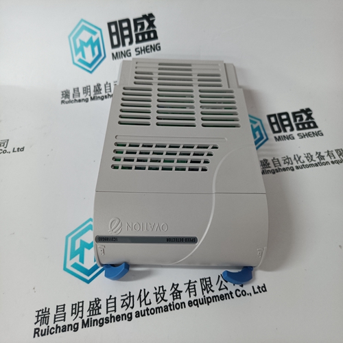
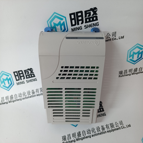
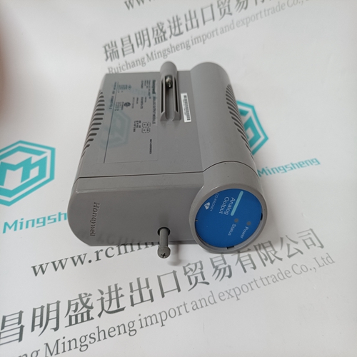
1C31189G03 Switch output module
- Product ID: 1C31189G03
- Brand: EMERSON
- Place of origin: The United States
- Goods status: new/used
- Delivery date: stock
- The quality assurance period: 365 days
- Phone/WhatsApp/WeChat:+86 15270269218
- Email:stodcdcs@gmail.com
- Tags:1C31189G03Switch output module
- Get the latest price:Click to consult
The main products
Spare parts spare parts, the DCS control system of PLC system and the robot system spare parts,Brand advantage: Allen Bradley, BentlyNevada, ABB, Emerson Ovation, Honeywell DCS, Rockwell ICS Triplex, FOXBORO, Schneider PLC, GE Fanuc, Motorola, HIMA, TRICONEX, Prosoft etc. Various kinds of imported industrial parts
Products are widely used in metallurgy, petroleum, glass, aluminum manufacturing, petrochemical industry, coal mine, papermaking, printing, textile printing and dyeing, machinery, electronics, automobile manufacturing, tobacco, plastics machinery, electric power, water conservancy, water treatment/environmental protection, municipal engineering, boiler heating, energy, power transmission and distribution and so on.

1C31189G03 Switch output module
Pulse enable/start inhibit When terminal 663 is energized, this initiates two functions: The pulse enable and inhibit are effective via an optocoupler input after 1 ms for a specific axis or for 2–axis modules, for a specific module. The start inhibit, terminal 663 open–circuit, acts with a delay of approx. 40 ms after terminal 663 is inhibited due to the drop–out delay of the start inhibit relay. The start inhibit supports safety–relevant functions, refer to Section 8.5. For pulse inhibit/start inhibit, the drives ”coast down” without being braked. Switch on terminal 663 after the ready signal of the power supply (terminals 72 to 74); when stopping after a power failure, terminal 663 must remain driven by means of the voltage backup until the motors have reached a standstill. Further, the 611D 1–axis and 2–axis modules and 611 universal HRS with PROFIBUS interface also have a pulse enable signal that acts on specific axes. The control is realized through NC/PLC interface signals via the digital drive bus or via the PROFIBUS DP interface. The signals are effective, delayed corresponding to the appropriate cycle times.
Start inhibit applications
The SIMODRIVE 611 drive control units support the ”safe standstill” function – this provides protection against unexpected starting according to the requirements of Appendix I No. 1.2.7 of the Machinery Directive 98/37/EC, DIN EN 954–1 Category 3 and DIN EN 1037. It is important that the information and the instructions in this documentation are precisely adhered to. For this purpose, the drive control units are provided by default with an internal safety relay with forced contacts. In the Configuration Manuals and user manuals, this safety relay is called a ”start inhibit” function or ”start inhibit relay.” This safety relay galvanically separates the power supply of the optocouplers for pulse transmission to the IGBT. The connected motor can no longer generate torque. The ”safe standstill” function prevents unexpected starting of the motor (from standstill) that is connected to the drive control unit. The motor shaft is in a no– torque condition when the ”safe standstill” function is active. This is the reason that this safety function should only be activated after the drive actually comes to a standstill. Otherwise, it will not be able to brake. The external machine control must have first brought the machine to a standstill and ensured that this has actually taken place (that the machine has come to a standstill).
Mode of operation of the start inhibit
The current through the individual motor windings is controlled using the inverter power module. The motors are fed with sinusoidal current. A pulse generation logic clocks the six power transistors in a rotating field–orientated pattern. An optocoupler for potential isolation is connected in each transistor arm between the control logic and the control (gating) amplifier of the power module. The start inhibit acts on each specific module. In each of the drive modules, a positively–driven relay in the inverter control acts in the input circuits of the optocouplers.
When the start inhibit function is correctly used, the forced signaling contact AS1/AS2 must always be included in the line contactor circuit or the EMERGENCY STOP circuit. If the function of the start inhibit relay is not plausible regarding the operating mode of the machine, then the drive involved must be electrically isolated from the line supply, e.g. using the line contactor in the infeed module. The start inhibit and the associated operating mode may only be re–used again after the fault has been removed.