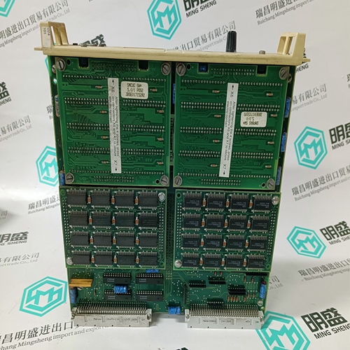
Home > Product > DCS control system > 1C31194G03 Switch input module
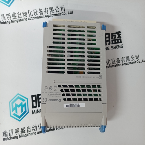
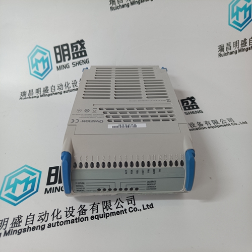
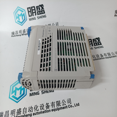
1C31194G03 Switch input module
- Product ID: 1C31194G03
- Brand: EMERSON
- Place of origin: The United States
- Goods status: new/used
- Delivery date: stock
- The quality assurance period: 365 days
- Phone/WhatsApp/WeChat:+86 15270269218
- Email:stodcdcs@gmail.com
- Tags:1C31194G03Switch input module
- Get the latest price:Click to consult
The main products
Spare parts spare parts, the DCS control system of PLC system and the robot system spare parts,Brand advantage: Allen Bradley, BentlyNevada, ABB, Emerson Ovation, Honeywell DCS, Rockwell ICS Triplex, FOXBORO, Schneider PLC, GE Fanuc, Motorola, HIMA, TRICONEX, Prosoft etc. Various kinds of imported industrial parts
Products are widely used in metallurgy, petroleum, glass, aluminum manufacturing, petrochemical industry, coal mine, papermaking, printing, textile printing and dyeing, machinery, electronics, automobile manufacturing, tobacco, plastics machinery, electric power, water conservancy, water treatment/environmental protection, municipal engineering, boiler heating, energy, power transmission and distribution and so on.

1C31194G03 Switch input module
A relay contact interrupts the power supply of the optocoupler inputs. This means that the optocoupler blocks and cannot transfer any signal. The pulse generation logic is inhibited using an additional branch that is electrically isolated. For the drive modules, these two circuits are controlled from the machine control through terminal 663 (motor start inhibit). The state of the relay contact in the pulse power supply circuit is signaled to the external adaptation circuit through a positively opening contact. The signaling contact is accessible at the module terminals AS1 and AS2 and the user can interlock this with his safety–relevant control. When the start inhibit fails, these start inhibit signaling contacts must disconnect the drive from the line supply via the power contactor in the line supply infeed (line contactor in the infeed module).When the start inhibit circuit is activated, it is no longer possible to gate several power transistors orientated to the rotating field.
When the start inhibit is active
the motor can no longer generate any torque. If external forces act on the drive axes, additional holding devices and equipment are required, e.g. brakes. Here, it is especially important to note the effect of gravity on hanging/suspended axes. The start inhibit does not result in electrical isolation. This means that under no circumstances does it provide protection against ”electric shock”. For operational interruptions, maintenance, servicing and cleaning work performed on the machine or plant, the complete machine must also be electrically isolated from the line supply using the line supply isolating device, e.g. main switch (see EN 60204–1; 5.3).
The start inhibit relay has pick–up and drop–out delay times of max. 40 ms. The external wiring must be connected to terminals AS1/AS2 so that it is short–circuit proof. One side of the excitation coil of the safety relay is connected to the grounded electronics chassis (PELV circuit according to DIN VDE 0160). When supplying the excitation coil (relay coil) from an external 24 V power supply, its negative pole must be connected to ground potential. The external 24 V power supply must fulfill the requirements for a PELV circuit in compliance with DIN VDE 0160.
Connecting–up the start inhibit
The start inhibit is addressed in the drive modules via terminal 663. The start inhibit relay is controlled using the internal enable voltage FR+ (terminal 9, +24 V)/or an external +24 V voltage. When using an external voltage source, its reference potential (ground) must be connected to FR– (terminal 19). When the relay is open, terminal 663 open, the start inhibit is activated. When the AS1/AS2 signaling contact is closed, this signals the ”start inhibit is effective” state with electrical isolation. The circuit must be protected against overload and short circuit using a fuse with a max. 2 A rating! When terminal 663 is externally controlled (drive), a fail–safe signal must be used.
Only qualified personnel may install and commission the ”safe standstill” function. All of the external safety–relevant cables, e.g. control cable for the safety relay, feedback signal contacts, must be routed so that they are protected, e.g. using cable ducts. The possibility of short–circuits and cross–circuits must be excluded.
