Home > Product > DCS control system > 1C31232G02 Voltage ac module
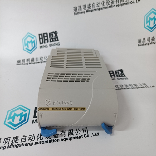
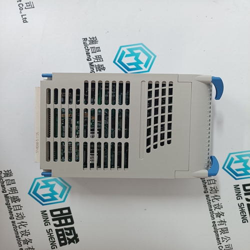
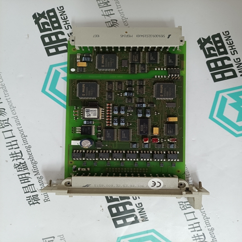
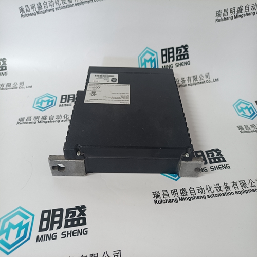
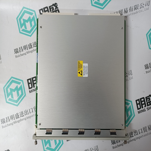
1C31232G02 Voltage ac module
- Product ID: 1C31232G02
- Brand: EMERSON
- Place of origin: The United States
- Goods status: new/used
- Delivery date: stock
- The quality assurance period: 365 days
- Phone/WhatsApp/WeChat:+86 15270269218
- Email:stodcdcs@gmail.com
- Tags:1C31232G02Voltage ac module
- Get the latest price:Click to consult
The main products
Spare parts spare parts, the DCS control system of PLC system and the robot system spare parts,Brand advantage: Allen Bradley, BentlyNevada, ABB, Emerson Ovation, Honeywell DCS, Rockwell ICS Triplex, FOXBORO, Schneider PLC, GE Fanuc, Motorola, HIMA, TRICONEX, Prosoft etc. Various kinds of imported industrial parts
Products are widely used in metallurgy, petroleum, glass, aluminum manufacturing, petrochemical industry, coal mine, papermaking, printing, textile printing and dyeing, machinery, electronics, automobile manufacturing, tobacco, plastics machinery, electric power, water conservancy, water treatment/environmental protection, municipal engineering, boiler heating, energy, power transmission and distribution and so on.

1C31232G02 Voltage ac module
Using two SIGUARD contactor safety combinations (A1. A2) for Emergency Stop and protective interlocking, it is possible to implement a configuration according to EN954–1 Control Category 3 and EN1037. Using the circuitry as shown in Fig. 8-9, a stop function, Category 1 according to EN 60204 is implemented. Switches S2 and S3 are positively–opening position switches corresponding to EN 1088. When the protective doors are opened, the contactor safety combinations trip, staggered in time and initiate that the drive is stopped in accordance with EN 60204–1 stop Category 1. Signal 0 is specified at the controller enable (CE) input of the drive by means of the enable contacts of the contactor safety combination A1. The drive is immediately decelerated to speed 0, and the pulses are canceled. The delay time of the contactor safety combination A1 is set so that the drive has come to a standstill when the delayed contacts open therefore initiating the second contactor safety combination A2.
The contactor safety combination A2
instantaneously de–energizes the safety relay in the drive via terminal 663. The feedback signal contacts of the safety relay must be closed after the selected delay time has expired, otherwise the drive is isolated from the line supply via terminal 48. For a protective door with tumbler mechanism, the drive is stopped with subsequent pulse cancellation, e.g. by pressing an appropriate button on the machine. The ”zero speed” signal releases the tumbler mechanism and when the protective doors open, the safety relay in the drive is immediately de–energized. In this particular case, the first timer stage (contactor safety combination A1) is not required. When the line supply is switched–in through K1 with button S1 ”power on” the correct functioning of the internal line contactor of the infeed unit is checked using the feedback signal in the power–on circuit.As long as the assigned protective device prevents any intervention in the hazardous zone, the feedback signal contacts of these power modules are jumpered. After the protective device has been opened, the drives must be shutdown in the defined time and the feedback signal contacts of the safety relay must be closed – otherwise, the higher–level main contactor will open
Function description of the application example
The block diagram, Section 8.6.1 shows an overview of an application example for a complete drive–related control of a machine with SIMODRIVE 611 drive components with analog setpoint interface. For information on versions with SIMODRIVE 611 digital and 611 universal, refer to Section 8.8. The individual applications and functions of the drive control are described in detail in the following Section 8.7 using circuit examples =1 to =9. The circuit examples =1 to =3 are provided for basic machine applications. Circuit examples =1 and =4 to =9 describe all of the essential functions that are used for a processing machine/machine tool. The circuit concept has been designed so that the individual control groups, from the basic function in circuit example =4 Drives on/off/stopping in an emergency situation; start/stop/safe standstill through additional functions Operating mode selection, automatic/setup mode with agreement =5 Protective door monitoring with tumbler mechanism =6 Limit switch, limit position monitoring =7 Armature short–circuit braking =8, and Power contactors in motor circuit =9 can be used for the particular applications, graduated from basic up to complex functions. When expanding the control system, step–by–step, up to the fully expanded configuration, the terminal jumpers, in the circuit examples, should be removed (interrupted), and the required interlocking and monitoring circuits inserted.