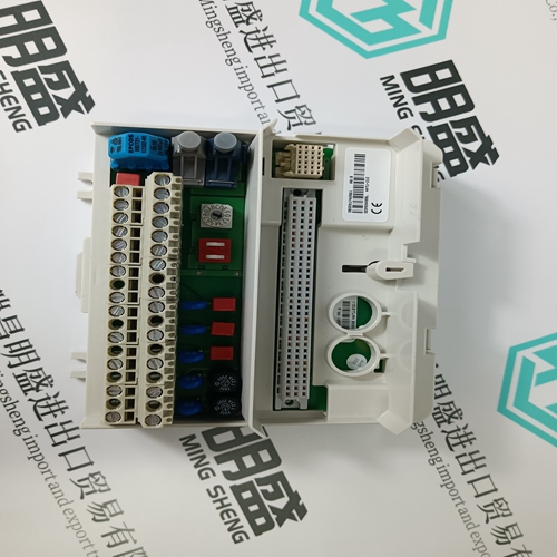
Home > Product > DCS control system > 5X00226G04 Channel interface module
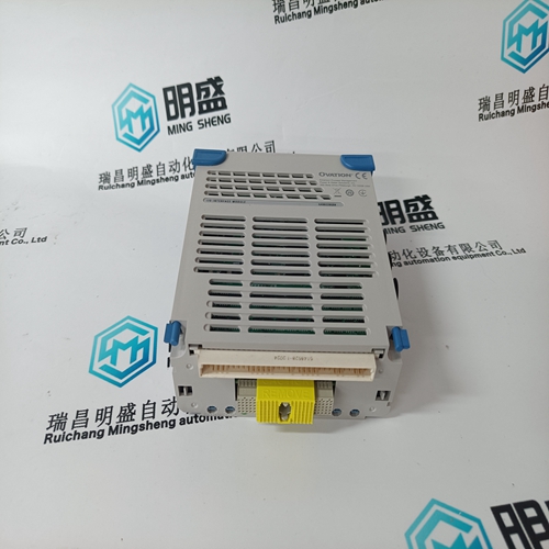
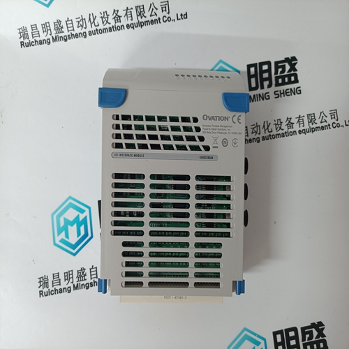
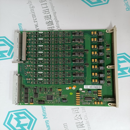
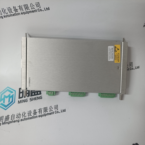
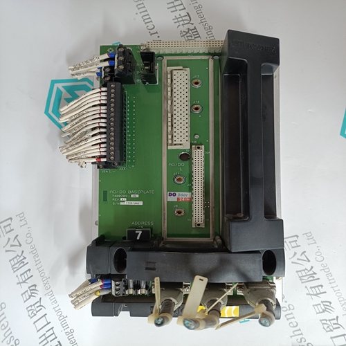
5X00226G04 Channel interface module
- Product ID: 5X00226G04
- Brand: EMERSON
- Place of origin: The United States
- Goods status: new/used
- Delivery date: stock
- The quality assurance period: 365 days
- Phone/WhatsApp/WeChat:+86 15270269218
- Email:stodcdcs@gmail.com
- Tags:5X00226G04Channel interface module
- Get the latest price:Click to consult
The main products
Spare parts spare parts, the DCS control system of PLC system and the robot system spare parts,Brand advantage: Allen Bradley, BentlyNevada, ABB, Emerson Ovation, Honeywell DCS, Rockwell ICS Triplex, FOXBORO, Schneider PLC, GE Fanuc, Motorola, HIMA, TRICONEX, Prosoft etc. Various kinds of imported industrial parts
Products are widely used in metallurgy, petroleum, glass, aluminum manufacturing, petrochemical industry, coal mine, papermaking, printing, textile printing and dyeing, machinery, electronics, automobile manufacturing, tobacco, plastics machinery, electric power, water conservancy, water treatment/environmental protection, municipal engineering, boiler heating, energy, power transmission and distribution and so on.

5X00226G04 Channel interface module
– The motor cannot be started accidentally. – The power feed to the motor is safely disconnected – The motor is not electrically isolated from the drive module or the converter DC link. The machinery construction OEM must take the appropriate measures to ensure that the drives do not undesirably move after the power feed has been disconnected. Secondary conditions, e.g. for vertical/suspended axes: – Safe standstill is only guaranteed if the kinetic energy stored in the machine cannot result in an unpredictable motion of the drives/axes. For example, for vertical or inclined axes without weight equalization, motion can occur as a result of non–symmetrical rotating bodies or workpieces. – The motor holding brake supports the safe standstill operating mode. – When manually intervening in the automatic mode, when traversing in setup mode, as well as during service/maintenance and repair work, depending on the hazard analysis, it may be necessary to apply additional measures for personnel and machinery protection. – Axes can be secured from dropping/falling or axes can be locked in a specific position using redundant devices in addition to the holding brake, e.g. using electromechanical or pneumatic locking devices with cyclic monitoring.
Application
Drive group, comprising an NE module, three 611 FD modules with High Standard control boards. This circuit concept can be used, for example, for basic drive controls. When the drives are powered up and powered down, the complete drive group, including the line contactor and start inhibit terminals, is switched in a safety–related fashion through two channels. Drives On Key–operated switch –S21, control on. The power–off circuit before the EMERGENCY STOP safety relay –K21 – with the expansion devices –K22, –K23 – must be switched–in taking into account the following conditions: Contactor –K25 closes, ready signal from the NE module. (ready conditions, NE module, refer to Section 6.2.5!) When the control is powered–up, the ready signal is still not present. This means that the PLC output O25 must be set to ”1” using the PLC logic so that the power–off circuit is closed through contactor –K25. After the drive group is switched in via the switching devices –K21, –K22, and –K23, the ready message is issued via PLC input I11, provided no error messages are pending.. The ready monitoring is now activated in the power–off circuit by means of the PLC logic. The feedback circuit from contactor –K25 is monitored using PLC I25. Contact =A1–A25/1–2 NC ready (ready signal) must be switched through to the NC control.
Interlock circuit terminal 35–36 is closed
The expansion devices –K22, –K23, the line contactor, the start inhibit functions/terminals and contactor –K27 for the brake control are now monitored, at each power–on cycle for the safety–related off switching condition. When required, safety–relevant functions of the machine control on the user side can also be incorporated in the feedback circuit. Pushbutton –S23, drives on Contactors –K21, –K22, –K23 are closed and power–up the drive group. After the DC link pre–charging has been completed, the line contactor in the NE module is closed. The ready message is issued as long as there is no error message present. NC program, start/stop Pushbutton –S29/–S28 The axis–specific controller enable signals are activated and the NC machining program is started using pushbutton –S29 NC program start. At the end of the program or using pushbutton –S28 – stop – the drives are brought to a controlled standstill.
