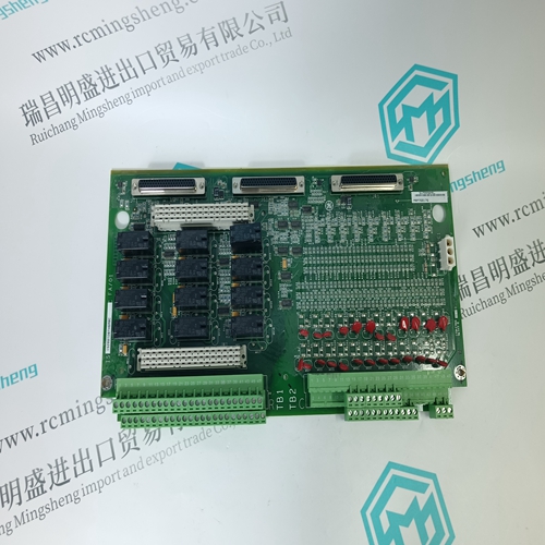
Home > Product > DCS control system > 5X00481G04 Channel module
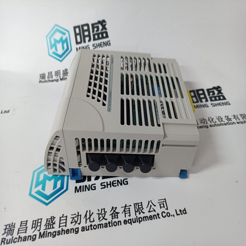
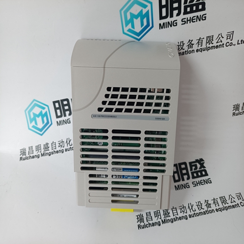
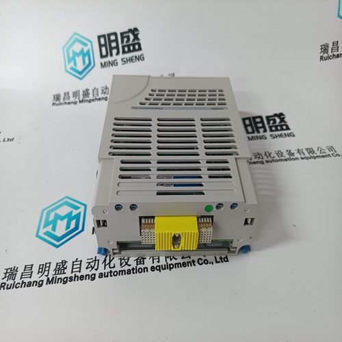
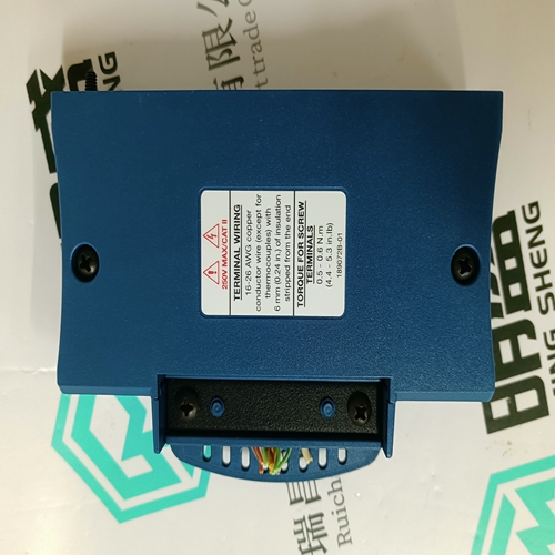
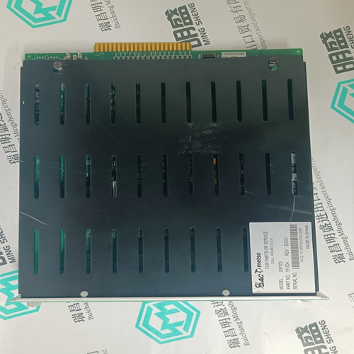
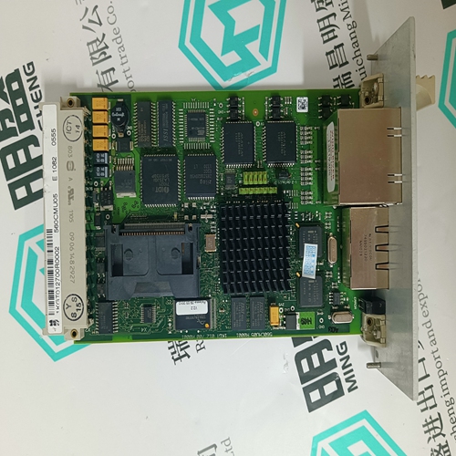
5X00481G04 Channel module
- Product ID: 5X00481G04
- Brand: EMERSON
- Goods status: new/used
- Delivery date: stock
- The quality assurance period: 365 days
- Phone/WhatsApp/WeChat:+86 15270269218
- Email:stodcdcs@gmail.com
- Tags:5X00481G04Channel module
- Get the latest price:Click to consult
The main products
Spare parts spare parts, the DCS control system of PLC system and the robot system spare parts,Brand advantage: Allen Bradley, BentlyNevada, ABB, Emerson Ovation, Honeywell DCS, Rockwell ICS Triplex, FOXBORO, Schneider PLC, GE Fanuc, Motorola, HIMA, TRICONEX, Prosoft etc. Various kinds of imported industrial parts
Products are widely used in metallurgy, petroleum, glass, aluminum manufacturing, petrochemical industry, coal mine, papermaking, printing, textile printing and dyeing, machinery, electronics, automobile manufacturing, tobacco, plastics machinery, electric power, water conservancy, water treatment/environmental protection, municipal engineering, boiler heating, energy, power transmission and distribution and so on.

5X00481G04 Channel module
Using pushbutton –S24 EMERGENCY STOP or –S22 Off, the drives, assuming that they have still not been stopped via the NC program, are braked and stopped as quickly as possible at the selected current limit of the drive modules. Terminal 64, drive enable, is inhibited and braking is initiated using the instantaneous contact of contactor –K22. After braking has been completed, the line contactor is opened using a safely overlapping shutdown time via the off delay contact of –K23 in a safety–relevant way through two channels via terminal 48 and NS1–NS2 of the line contactor; the drive inhibit functions are activated by inhibiting terminals 663. Fault signals of the drive system, interlocked using the PLC logic can be used, depending on the application, to brake along the current limit or for controlled braking along a setpoint ramp. The Off button also acts on PLC I22. This means PLC logic can be used to determine which switch–off command caused the drive group to be shutdown. The drive group can also be powered down via the PLC, logically combined, independent of the ready signal of the NE module using contactor –K25.
Holding brake
The holding brake is controlled, coordinated as far as the timing is concerned by the PLC logic through PLC O27. When the drives are stopped, the brake is additionally safely shutdown per hardware using an off delay contact of contactor –K23. This means that a PLC fault, when the drive is stationary, cannot cause the brake to be incorrectly controlled. Temperature sensor If the temperature monitoring is tripped because of overtemperature of a drive module and/or a motor, the 5.1–5.3 relay contact on the NE module activates the PLC–E12 input. Using the logical interlocking in the PLC, the drives must, depending on the application, be shutdown either instantaneously or delayed, e.g. using PLC O25 and contactor –K25.This control is used where one or several drives must be selectively shut down from an operational drive group using safety–relevant technology. The drive can be shutdown in a safety–relevant way from the drive group using a two–channel key–operated switch or, e.g. using light barriers or limit switches. Beforehand, the drive must have been safely stopped by the NC control. The ”safe standstill” condition is achieved using the start inhibit function.
Drives, start
The 2–channel stop circuit in front of safety relay –K11 must be closed using the key–operated switch –S11 and the EMERGENCY STOP circuit contactor =2–K22. Contactor –K11 is closed with ”monitored start” and latches using button –S12 – start – and the closed feedback circuit. Terminal 65, controller enable, and terminal 663, pulse enable, are energized. The drive is moved and stopped in a controlled way using the NC program. Stop drives Safety relay –K11 is de–energized using key–operated switch –S11 or when EMERGENCY STOP is pressed. The instantaneous contact withdraws terminal 65 ”controller enable” and the drive is braked at the current limit. Terminal 663 is de–energized via the off delay contact –K11 and therefore the start inhibit activated. Start inhibit monitoring function The start inhibit monitoring function for terminals 35–36 is effective in the EMERGENCY STOP circuit of contactor =K2–K21. Normally, when a drive is stopped, the NC contact AS1–AS2 of the start inhibit relay should always be closed before the NO contact of contactor –K13 opens. To ensure this, the contactor coil –K13 must be equipped with a diode to extend the contactor off delay. If the start inhibit function is incorrect, the monitoring circuit opens and disconnects the complete drive group through the line contactor. The start inhibit is actively monitored in a cyclic manner after every stop operation. Holding brake The function is similar to that in circuit example =2
