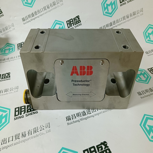
Home > Product > DCS control system > 5X00489G01 Thermal resistance module
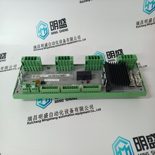
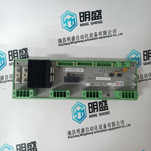
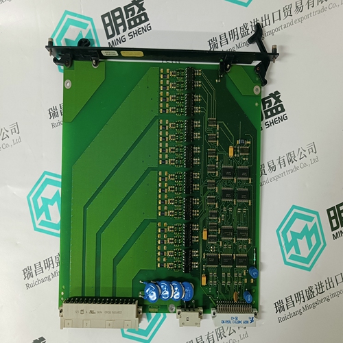
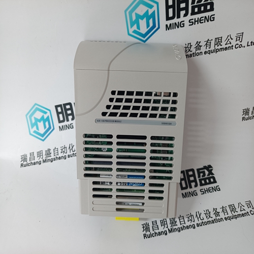
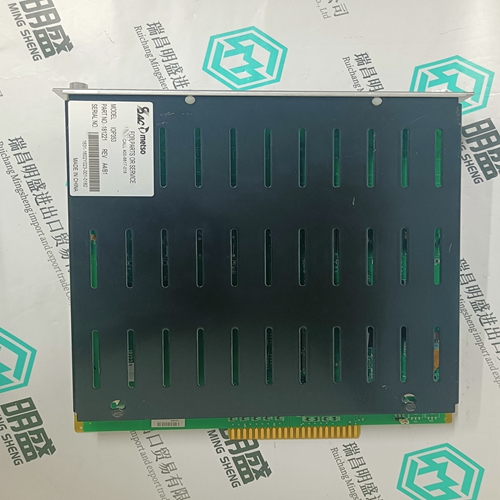
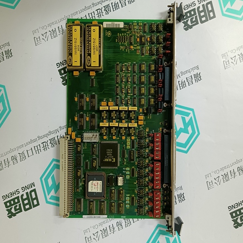
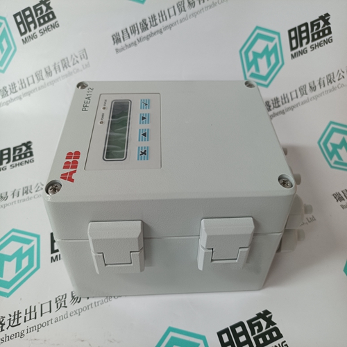
5X00489G01 Thermal resistance module
- Product ID: 5X00489G01
- Brand: EMERSON
- Place of origin: The United States
- Goods status: new/used
- Delivery date: stock
- The quality assurance period: 365 days
- Phone/WhatsApp/WeChat:+86 15270269218
- Email:stodcdcs@gmail.com
- Tags:5X00489G01Thermal resistance module
- Get the latest price:Click to consult
The main products
Spare parts spare parts, the DCS control system of PLC system and the robot system spare parts,Brand advantage: Allen Bradley, BentlyNevada, ABB, Emerson Ovation, Honeywell DCS, Rockwell ICS Triplex, FOXBORO, Schneider PLC, GE Fanuc, Motorola, HIMA, TRICONEX, Prosoft etc. Various kinds of imported industrial parts
Products are widely used in metallurgy, petroleum, glass, aluminum manufacturing, petrochemical industry, coal mine, papermaking, printing, textile printing and dyeing, machinery, electronics, automobile manufacturing, tobacco, plastics machinery, electric power, water conservancy, water treatment/environmental protection, municipal engineering, boiler heating, energy, power transmission and distribution and so on.

5X00489G01 Thermal resistance module
Stop drives Using the two–channel pushbutton –S31, drives stop – the drives are braked and stopped as quickly as possible at the selected current limit of the drive modules if these have not already been stopped by the NC program. Terminal 64 – drive enable – is de–energized by the instantaneous contact of contactor –K31. After the drives have come to a standstill, terminal 663 is inhibited and the start inhibit functions become active via the off delay contacts of the safety relays –K32 and –K35. The shutdown times are adapted to the various braking times of the MSD and FD drives and must safely overlap these from a time perspective, e.g. MSD 5 s; FD 0.5 s.
The NE module must be powered up. The stop circuit in front of safety relay –K31 must be closed. The interlocking circuits of the following expansions of circuit =5 are jumpered. Using pushbutton –S32 – drives, start (monitored start) – with the feedback circuit closed, safety relay –K31 with expansion device –K32 and contactors –K35, –K33, –K36 are closed and latch. Simultaneously, terminal 63 central pulse enable, terminal 64 ”drive enable” at the NE module and terminal 663 ”pulse enables ” for the drive modules are energized and therefore the start inhibit functions are withdrawn. NC program, start/stop Pushbutton –S29/–S28 The axis–specific controller enable signals are activated and the machining program is started using pushbutton –S29 NC program start. At the end of the program or using pushbutton –S28 – stop – the drives are brought to a controlled standstill.
Start inhibit monitoring function
The start inhibit monitoring function for terminals 37–38 is effective in the EMERGENCY STOP circuit of contactor –K21. Normally, when the drives stop, the NC contacts AS1–AS2 of the start inhibit relays in the drive modules must always be closed before the NO contact of contactors –K33 and –K36 open. In order to realize this, the coils of these contactors must be equipped with a diode to extend the contactor drop–out delay. If the start inhibit function is incorrect, the monitoring circuit opens, EMERGENCY STOP contactor –K21 drops out and shuts down the complete drive group through the line contactor. The start inhibits are actively monitored in a cyclic manner after every stop operation. Drives Off Using the EMERGENCY STOP pushbutton –S24 or Off –S22 – the drives are braked and stopped as quickly as possible at the current limit. The function is similar in circuit diagram =2. After the braking time of the spindle drive, the –K31/–K32 contactor is used to switch off the drive group, i.e. line contactor off and start inhibits active.
operation with agreement
The operating mode changeover is used for most machines/plants, e.g. in setup mode, in order to traverse/operate sub–functions of the machine at a controlled, reduced velocity. In this particular operating mode, other sub–areas must be shutdown in a safety–related way to avoid potential hazards. The drives can only be operated with an agreement issued by the operator in the setting–up mode with reduced velocity/speed. This agreement can, for example, depending on the risk assessment, be issued from a secure location outside the hazardous zone of the machine or using a mobile hand–held unit with additional EMERGENCY STOP pushbutton in the operating zone of the machine. Notice In this case, the user is responsible for observing and complying with the specific technological and machine–specific regulations and standards to maintain the protection and safety of personnel and machinery. Further, residual risks must be evaluated – those risks that are due for example to vertical axes. The start phase of the machine after power–on is especially critical. An agreement for a specific traversing motion should only be issued if the machine had previously moved in a controlled way.
