Home > Product > DCS control system > 5X00499G01 Channels of contact module
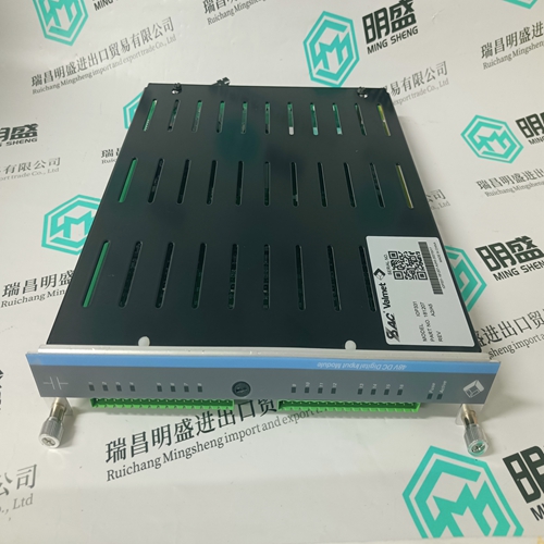
5X00499G01 Channels of contact module
- Product ID: 5X00499G01
- Brand: EMERSON
- Place of origin: The United States
- Goods status: new/used
- Delivery date: stock
- The quality assurance period: 365 days
- Phone/WhatsApp/WeChat:+86 15270269218
- Email:stodcdcs@gmail.com
- Tags:5X00499G01Channels of contact module
- Get the latest price:Click to consult
The main products
Spare parts spare parts, the DCS control system of PLC system and the robot system spare parts,Brand advantage: Allen Bradley, BentlyNevada, ABB, Emerson Ovation, Honeywell DCS, Rockwell ICS Triplex, FOXBORO, Schneider PLC, GE Fanuc, Motorola, HIMA, TRICONEX, Prosoft etc. Various kinds of imported industrial parts
Products are widely used in metallurgy, petroleum, glass, aluminum manufacturing, petrochemical industry, coal mine, papermaking, printing, textile printing and dyeing, machinery, electronics, automobile manufacturing, tobacco, plastics machinery, electric power, water conservancy, water treatment/environmental protection, municipal engineering, boiler heating, energy, power transmission and distribution and so on.

5X00499G01 Channels of contact module
For dynamic drives with inadmissible speed increases, potential hazards can occur under fault conditions due to the response times of personnel and the delay when the agreement device switches. These hazards must be reduced by applying additional measures, e.g. a safety–related speed monitoring function. Various type C Standards, e.g. for machine tools, specify a safely monitored speed in the setting–up mode for spindle drives.
In the automatic mode, the working zone of a machine is isolated using a moving, closed protective door (e.g. guard). In the circuit example, the protective door is interlocked and cannot be opened while the drives are running or if other hazardous operating states exist. This is realized using a position switch with tumbler mechanism with an interlock using spring force with sealed auxiliary release. Automatic operation for the drives is only enabled if the protective door is closed and interlocked via the position switch. Depending on the hazard analysis, the user must decide whether, e.g. a second limit switch is additionally required for the door monitoring function.
Opening the protective door
By opening the protective door, the protective door safety circuit is opened via the actuator of the door position switch –S11 – redundantly to the position monitoring function of the solenoids. Closing the protective door The protective door must be closed. Using pushbutton –S16 – interlock protective door – contactors –K15/–K16 are de–energized (they drop–out) and the protective door is again interlocked. The interlock circuit is again closed through terminals 611–612/613–614 which means in the selected automatic mode, the drives can again be released using pushbutton =4–S32 – start. For protective doors that are infrequently opened, we recommend that the control is adapted so that each time before the drives are powered up, the position switch function is checked by opening and again closing the door.
The protective door is prevented from being opened as long as a hazardous state exists, e.g. as a result of the drives running–down. The enable signal is only issued with a time delay after the drive with the longest braking time has been reliably and safely stopped or optionally using the standstill signal of an external speed monitoring function. For several applications, e.g. if personnel can enter the working area of a machine, the tumbler mechanism of the protective door is implemented using a position switch interlocked with magnetic force. This is for safety–related reasons. When the line supply or control voltage fails, the position switch can be used to release the protective door and allow it to be opened.
Request protective door enable
The drives must initially be shutdown using pushbutton =4–S31 – stop drives – or optionally, e.g. at the end of the NC program by the output of an NC auxiliary function, PLC O18 closes contactor –K18. The protective door enable is requested using pushbutton –S15. Contactor – K15 is activated, interlocked through the PLC logic when the drives are stopped and shut down. This means that contactors =4–K33 and =4–K36 have dropped out. PLC logic: PLC O15 = ”1”, if =4–I33 and =4–I36 = ”0” signal. When requesting that the protective door is enabled, in the secured working zone of the machine/plant, all hazardous motion and other potential hazards of the user–side machine control must be shutdown. The shutdown must then realized in a safety–relevant way using the released or opened protective door. Releasing the protective door The protective door is released using contactor –K16 if the following conditions are fulfilled: Contactor –K15 is closed (energized) Drives, delayed stop, contactors =4–K33 and =4–K36 open (de–energized). MSD standstill signal n act < n min via relay =4–K11. User–side interlocking circuit is closed via terminal 601–602.