Home > Product > DCS control system > 1C31179G02 Transmitter input module
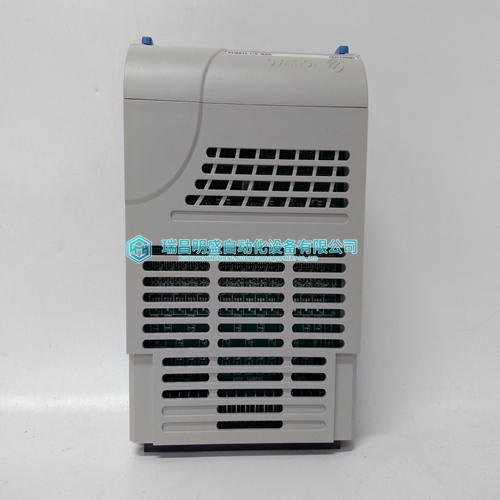
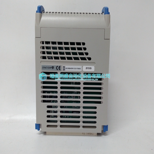
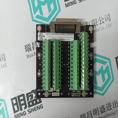
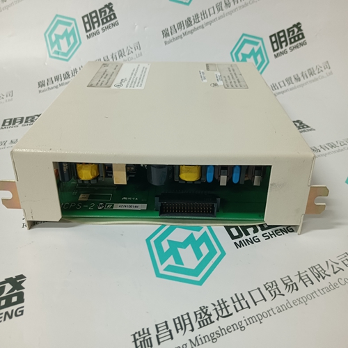
1C31179G02 Transmitter input module
- Product ID: 1C31179G02
- Brand: EMERSON
- Place of origin: The United States
- Goods status: new/used
- Delivery date: stock
- The quality assurance period: 365 days
- Phone/WhatsApp/WeChat:+86 15270269218
- Email:stodcdcs@gmail.com
- Tags:1C31179G02Transmitter input module
- Get the latest price:Click to consult
The main products
Spare parts spare parts, the DCS control system of PLC system and the robot system spare parts,Brand advantage: Allen Bradley, BentlyNevada, ABB, Emerson Ovation, Honeywell DCS, Rockwell ICS Triplex, FOXBORO, Schneider PLC, GE Fanuc, Motorola, HIMA, TRICONEX, Prosoft etc. Various kinds of imported industrial parts
Products are widely used in metallurgy, petroleum, glass, aluminum manufacturing, petrochemical industry, coal mine, papermaking, printing, textile printing and dyeing, machinery, electronics, automobile manufacturing, tobacco, plastics machinery, electric power, water conservancy, water treatment/environmental protection, municipal engineering, boiler heating, energy, power transmission and distribution and so on.

1C31179G02 Transmitter input module
An essential criterion when implementing power failure concepts is to be able to quickly detect a line supply fault (power failure, line supply undervoltage or phase failure). When a line supply fault occurs, the DC link voltage quickly dips/fails due to the power drawn by the drives and the connected power supplies for the drive and control components. The discharge time depends on the DC link capacity, the charge (voltage) and the loading after the power failure. Operation when the power fails with initiation of the regenerative feedback of one or more drives into the DC link must become effective before the DC link voltage decreases below the rated voltage, e.g. 600 V DC to 350 V DC. At approx. 350 V, the pulses are internally inhibited in the drive group, and the drives coast down. The DC link voltage of 600 V DC is proportionally emulated at the control level and can be evaluated in the 611 digital and 611 universal control units via the equipment bus. The DC link voltage can be monitored to provide a fast response using parameterizable limit value stages, e.g. to 450 – 500 V. This therefore allows indirectly, an immediate response to be made to a line supply fault, e.g. power failure
Application and mode of operation
The function ”operation with the power fails” (power failure buffering) is used, for example, for machines where personnel could be in danger or significant machine damage could occur due to a danger of collision when machining due to power failure or for internal control fault signals. Further, the function is used for machines with complex machining operations. For example, when machining gear wheels (hobbing, roller grinding) where expensive tools and workpieces are used and which should be protected from possible damage if power failures were to occur. For operation when the power fails, stopping and/or retracting drive motion, the energy stored in the capacitors of the power DC link and the kinetic energy of the moved masses stored when the drives regenerate into the line supply can be briefly used. To do this, a connection must be established from the power DC link P600/M600 to the auxiliary power supply via the terminals P500/M500 in the NE module or in the monitoring module. Further, additional circuit measures are required. For example, the control voltages must be buffered and a power failure and/or DC link monitoring function to initiate the appropriate control functions. After a hazard analysis, the machinery construction OEM must evaluate these risks and requirements and apply appropriate measures to avoid such hazards or damage. The requirements placed on the power failure concepts differ significantly depending on the user and machine and must therefore be individually engineered.
The ready signal via terminals 72–74
in the NE module also responds when a line supply fault occurs and inhibits the pulses in the NE module. The response time is, among other things, dependant on the line supply impedances and other quantities and can therefore not be precisely calculated in advance. Generally, the power failure detection time is >30 ms and is alone not sufficient to initiate functions for operation when the power fails (line supply failure). Operation when the power fails with the SIMODRIVE 611 universal HRS Example: The DC link voltage is monitored using the limit value stage of a 611 universal HRS control board in the SIMODRIVE 611 universal HRS. When a selectable limit value is undershot, e.g. a DC link voltage of 550 V, the limit value stage responds and switches a positive output signal from +24 V to 0 V via a digital output stage. For example, terminal 64 – drive enable – can be inhibited in an ”AND” logic operation with the relay contact of the ready signal of terminals 72–73.1 of the NE module. The drives are braked and stopped as quickly as possible at the current limit. In addition, for example, via a second digital output of the 611 universal module, the setpoint polarity of a drive can be changed–over and retraction motion initiated for a drive before the other remaining drives are braked, delayed via terminal 64.