Home > Product > DCS control system > PE1315A controller card
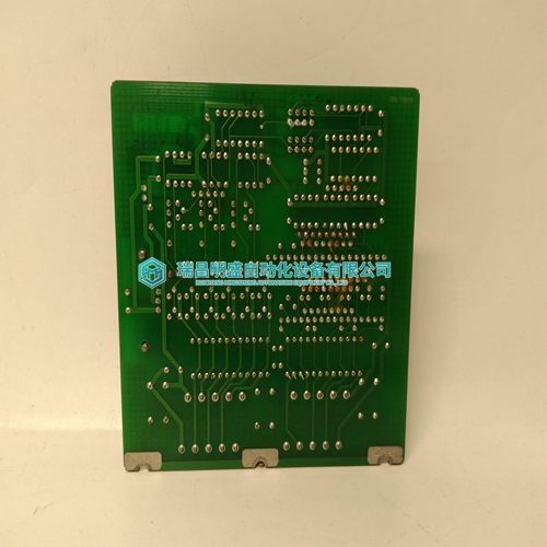
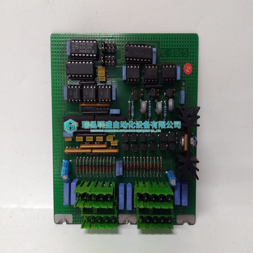
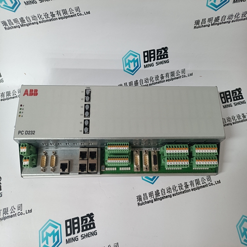
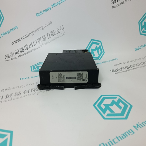
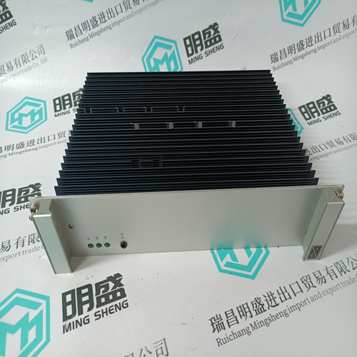
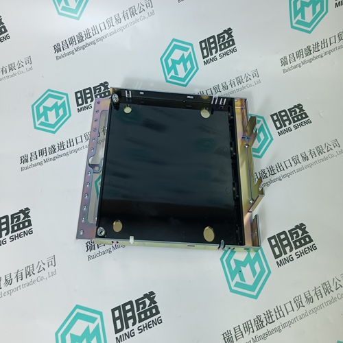
PE1315A controller card
- Product ID: PE1315A
- Brand: ABB
- Place of origin: The Swiss
- Goods status: new/used
- Delivery date: stock
- The quality assurance period: 365 days
- Phone/WhatsApp/WeChat:+86 15270269218
- Email:stodcdcs@gmail.com
- Tags:PE1315Acontroller card
- Get the latest price:Click to consult
The main products
Spare parts spare parts, the DCS control system of PLC system and the robot system spare parts,Brand advantage: Allen Bradley, BentlyNevada, ABB, Emerson Ovation, Honeywell DCS, Rockwell ICS Triplex, FOXBORO, Schneider PLC, GE Fanuc, Motorola, HIMA, TRICONEX, Prosoft etc. Various kinds of imported industrial parts
Products are widely used in metallurgy, petroleum, glass, aluminum manufacturing, petrochemical industry, coal mine, papermaking, printing, textile printing and dyeing, machinery, electronics, automobile manufacturing, tobacco, plastics machinery, electric power, water conservancy, water treatment/environmental protection, municipal engineering, boiler heating, energy, power transmission and distribution and so on.

PE1315A controller card
The instantaneous output (14) of –A3 switches–out (de–energizes) safety relay –K1 via –K6. (the drive pulses are canceled and in turn the energy feed to the motor is interrupted). The NC contact of –K1 controls contactor relay –K3. The NO contact of –K3 in parallel with –K4 closes and keeps line contactor –K2 connected to the power supply via –K5. After the time selected in –A3 expires, the delayed output (28) switches–out (de–energizes) contactor relay –K4. Line contactor –K2 remains controlled (energized) from –K5 via –K3. The DC link remains charged via terminal 4. –K1 is automatically controlled (energized) from –K6 via –A3. –K2 is again controlled (energized) from –K5 using –K4 via –A3. High signal at the controller enable input of the drive. –> motor can be operated again.
The instantaneous output (14) of safety relay –A1 is de–energized, and therefore the cascading input (1) of –A2 is deactivated. –A2 behaves just the same as when opening the protective door
Actuating EMERGENCY STOP
After the selected time at –A2 has expired, the delayed output (28) switches the cascading input (1) from –A3 to a low signal level. The instantaneous output (14) of –A3 switches–out (de–energizes) safety relay –K1 via –K6. (the drive pulses are canceled and in turn the energy feed to the motor is interrupted). The delayed output (28) of –A1 switches–out (de–energizes) line contactor –K2 after the selected time. This behavior corresponds to stop Category 1, according to EN 60204–1:2006. The drive must be stopped within the delay time set at –A2. If the pulses are canceled before the drive comes to a standstill, then the drive will coast down. The time at –A3 should be set as short as possible, however so that –K3 pulls in before –K4 drops out in order to avoid that line contactor –K2 drops out. The delay time at –A1 should be set the same as the time of –A2.If the protective door is opened, the drive should be safely stopped and after a safely monitored time, should be shut down.
EVALUATE subsystem
In this example, the EVALUATE subsystem is implemented in the form of two SIRIUS 3TK2842 safety relays. The safety relays have instantaneous and delayed electromechanical enable circuits. Device –A3 is used to provide a safety–related time delay when switching off and is controlled via the cascading input, terminal 1. Both devices –A2 and –A3, are used to evaluate the door switch and the feedback signals from the contactor relays.
The RESPOND subsystem has a two channel structure. The first channel comprises safety relay –K1 and contactor relay –K6. Line contactor –K2 and contactor relays –K3, –K4 and –K5 form the second channel. In this example, the RESPOND subsystem has a two channel structure with different demand rates per channel. A dangerous fault in channel 1 means that channel 2 is immediately called with its monitoring options. Components –K1, –K3, –K4 and –K6 are tested by –A2 or –A3 at each start. Contactor –K2 and contactor relay –K5 are tested by –A1 at each start. An accumulation of faults in channel 2 between two consecutive actuations of the EMERGENCY STOP pushbutton is not detected. Basic as well as well–proven safety principles – such as the requirements regarding Category B – are maintained. Protective circuits are provided. Protective circuits are provided. When a component fails, the safety function is always maintained. The failure is detected.