Home > Product > Gas turbine system > VMIVME-4116 Gas turbine electrical module
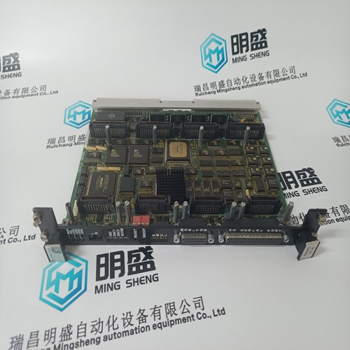
VMIVME-4116 Gas turbine electrical module
- Product ID: VMIVME-4116
- Brand: GE
- Place of origin: the United States
- Goods status: new/used
- Delivery date: stock
- The quality assurance period: 365 days
- Phone/WhatsApp/WeChat:+86 15270269218
- Email:stodcdcs@gmail.com
- Tags:VMIVME-4116Gas turbine electrical module
- Get the latest price:Click to consult
The main products
Spare parts spare parts, the DCS control system of PLC system and the robot system spare parts,Brand advantage: Allen Bradley, BentlyNevada, ABB, Emerson Ovation, Honeywell DCS, Rockwell ICS Triplex, FOXBORO, Schneider PLC, GE Fanuc, Motorola, HIMA, TRICONEX, Prosoft etc. Various kinds of imported industrial parts
Products are widely used in metallurgy, petroleum, glass, aluminum manufacturing, petrochemical industry, coal mine, papermaking, printing, textile printing and dyeing, machinery, electronics, automobile manufacturing, tobacco, plastics machinery, electric power, water conservancy, water treatment/environmental protection, municipal engineering, boiler heating, energy, power transmission and distribution and so on.

VMIVME-4116 Gas turbine electrical module
This safety function corresponds, regarding its implementation, the explanation and information given in Chapter 9.4.2 ”Supplementary safety function EMERGENCY STOP for an axis”. Only in the RESPOND area, in channel 1, the additional safety relay –K1 has been added. This must also be taken into account when calculating the RESPOND subsystem.The circuit examples in Chapter 9.4 ”Application examples” are, for reasons of transparency, configured using separate safety relays. The logic component of the described safety functions can be implemented using programmable safety components, such as a fail–safe PLC systems, or the modular MSS safety system. The safety relays can be monitored using software in the logic section. This means that the contactor relays can be eliminated.1. Switch off the line current supplies (I/R module) or DC link voltage (PM module). Wait at least 30 minutes for the DC link energy to discharge! 2. Verify that the fan is isolated from the supply (line supply input and DC link)! 3. Remove the components from the drive group. 4. Open the fan cover
Connection Diagrams
The following connection diagrams only show the terminal connections. Further, external components are not completely shown. Refer to Chapter 8. The following comments should be observed in the connection diagrams: 1. The jumper may only be removed in conjunction with the start inhibit. 2. Not available for unregulated infeed. 3. Connect with terminal 19 of the NE module. 4. Drive bus – round cable 5. Drive bus – ribbon cable 6. Drive bus – terminating connector 7. For an external pulsed resistor, remove jumper 1R/2R The serial number is stamped on the type plate. When forming, the DC link capacitors are subject to a defined voltage and a limited current. This means that the internal relationships required for the DC link capacitors to function are restored.
The forming circuit is configured using incandescent lamps, or alternatively using PTC resistors. Components required (recommendation): 1 fuse switch 3x 400 V / 10 A Cable, 1,5 mm2 3 PTC resistors 350 R / 35 W (Recommended: PTC–35W PTC800620–350 Ohm, company, Michael Koch GmbH; www.koch–mk.de 3 incandescent lamps 230 V / 100 W Various small parts, such as lamp sockets, etc.
Procedure
Before forming the DC link capacitors, it is imperative that the DC link bridge is removed. Ensure that the power module does not receive a switch–on command. Connect the forming circuit. Over the course of the forming time, the incandescent lamps must become darker/go out completely. If the incandescent lamps are continually lit, then there is a fault in the power module the wiring. When forming using PTC resistors, the modules must remain in the circuit for approximately 1 hour. If there is a fault in the power module, then the resistors will become very hot (surface temperature > 80 °C).The EMC limit values to be complied with for South Korea correspond to the limit values of the EMC product standard for variable–speed electric drives EN 61800–3, Category C2 or limit value class A, Group 1 according to EN55011. By applying suitable supplementary measures, the limit values according to Category C2 or according to limit value class A, Group 1 are maintained. Further, additional measures may be required, for instance, using an additional radio interference suppression filter (EMC filter). The measures for EMC-compliant design of the system are described in detail in this manual respectively in the Installation Guideline EMC. Please note that the final statement on compliance with the standard is given by the respective label attached to the individual unit.