Home > Product > DCS control system > 216AB61 HESG324013R0100 HESG435572P1 Excitation module
216AB61 HESG324013R0100 HESG435572P1 Excitation module
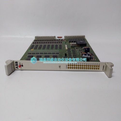
- Product ID: 216AB61 HESG324013R0100 HESG435572P1
- Brand: ABB
- Place of origin: The Swiss
- Goods status: new/used
- Delivery date: stock
- The quality assurance period: 365 days
- Phone/WhatsApp/WeChat:+86 15270269218
- Email:stodcdcs@gmail.com
- Tags:216AB61 HESG324013R0100HESG435572P1Excitation module
- Get the latest price:Click to consult
The main products
Spare parts spare parts, the DCS control system of PLC system and the robot system spare parts,Brand advantage: Allen Bradley, BentlyNevada, ABB, Emerson Ovation, Honeywell DCS, Rockwell ICS Triplex, FOXBORO, Schneider PLC, GE Fanuc, Motorola, HIMA, TRICONEX, Prosoft etc. Various kinds of imported industrial parts
Products are widely used in metallurgy, petroleum, glass, aluminum manufacturing, petrochemical industry, coal mine, papermaking, printing, textile printing and dyeing, machinery, electronics, automobile manufacturing, tobacco, plastics machinery, electric power, water conservancy, water treatment/environmental protection, municipal engineering, boiler heating, energy, power transmission and distribution and so on.

216AB61 HESG324013R0100 HESG435572P1 Excitation module
The B849–016 48 V ac/dc input module senses OFF and ON input signals from its field circuitry, converting them to logic levels used by a PLC. The module’s 16 input circuits are divided into two groups of eight channels, each group totally isolated from the other. Although both groups use common return wires, none has a definite relationship to system ground unless established in the user’s field circuitry. Since both groups nominally employ independent power return sources, both ac and dc powered field circuits may input to the module at the same time.
When the user’s ac/dc powered field circuit goes ON — as the result of a limit for example — it presents the field power voltage at the modules appropriate input channel. When the input voltage meets or exceeds the module’s guaranteed ON threshold, the resulting voltage turns the channel monitor lamp ON, current flows through the bridge rectifier and subsequently the opto-isolator (OPTO-ISOL) circuit. Given a nominal 115 Vac/125 Vdc field power supply and a kΩ maximum input source impedance, the module’s channel monitor lamps will indicate ON and OFF when input voltages are 80 Vac/85 Vdc for the high level ON; and 35 Vac/40 Vdc for the low level OFF respectively.
The optical energy goes
to the communications board (COMM BOARD) where the OURBUS output register is set to represent the field circuit’s ON state. As long as the field input status remains true, the module will communicate this status each time it is polled by the controller. Total scan time may be as long as 250 ms. The user should not attempt to monitor events with a repetition rate greater than 1/s without analyzing his actual system, program, and scan time.True High Input Module B853–016 115-Vac/125-Vdc senses OFF and ON input signals from its field circuitry, converting them to logic levels used by a Modicon PLC. The module’s 16 input circuits are divided into two groups of eight channels, each group being totally isolated from the other. Although both groups use common return wires, none has a definite relationship to system ground unless established in the user’s field circuitry. Since both groups nominally employ independent power return sources, both ac and dc powered field circuits may directed to the module at the same time.
Simplified Block Diagram
When the user’s ac/dc powered field circuit goes ON—as the result of a limit switch, for example—it presents the field power voltage at the module’s appropriate input channel. When the input voltage meets or exceeds the module’s ON threshold, the resulting voltage turns the channel monitor lamp ON, current flows through the bridge rectifier and subsequently the opto-isolator (OPTO-ISOL) circuit. Given a nominal 115 Vac/125 Vdc field power supply and a kΩ maximum input source impedance, the module’s channel monitor lamps will indicate ON and OFF when input voltages are 80 Vac/85 Vdc for the high level ON; and 35 Vac/40 Vdc for the low level OFF respectively. The optical energy goes to the communications board (COMM BOARD) where the OURBUS output register is set to represent the field circuit’s ON state. As long as the field input status remains true, the module will communicate this status each time it is polled by the controller. Total scan time may be as long as 250 ms. The user should not attempt to monitor events with a repetition rate greater than 1/s without analyzing his actual system, program, and scan time.