Home > Product > DCS control system > 216DB61 HESG324063R0100 HESG216882A Excitation card
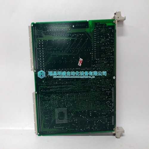
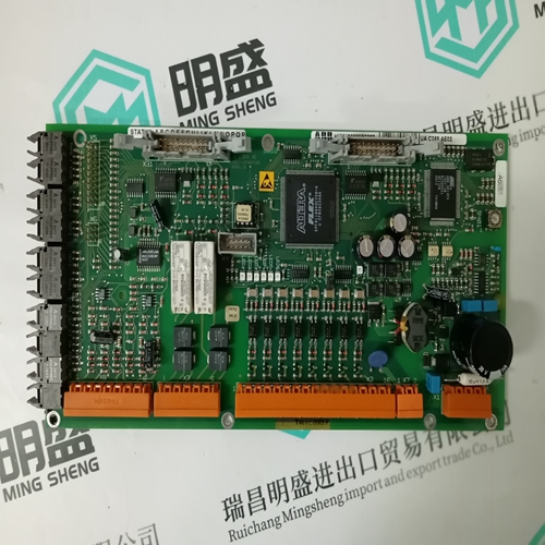
216DB61 HESG324063R0100 HESG216882A Excitation card
- Product ID: 216DB61 HESG324063R0100 HESG216882A
- Brand: ABB
- Place of origin: The Swiss
- Goods status: new/used
- Delivery date: stock
- The quality assurance period: 365 days
- Phone/WhatsApp/WeChat:+86 15270269218
- Email:stodcdcs@gmail.com
- Tags:216DB61 HESG324063R0100HESG216882AExcitation card
- Get the latest price:Click to consult
The main products
Spare parts spare parts, the DCS control system of PLC system and the robot system spare parts,Brand advantage: Allen Bradley, BentlyNevada, ABB, Emerson Ovation, Honeywell DCS, Rockwell ICS Triplex, FOXBORO, Schneider PLC, GE Fanuc, Motorola, HIMA, TRICONEX, Prosoft etc. Various kinds of imported industrial parts
Products are widely used in metallurgy, petroleum, glass, aluminum manufacturing, petrochemical industry, coal mine, papermaking, printing, textile printing and dyeing, machinery, electronics, automobile manufacturing, tobacco, plastics machinery, electric power, water conservancy, water treatment/environmental protection, municipal engineering, boiler heating, energy, power transmission and distribution and so on.
216DB61 HESG324063R0100 HESG216882A Excitation card
The B855–016 Intrinsically Safe (fully isolated) Input Module accepts 16 switch closures or low impedance discrete inputs less than 100 Ω and operates in any 800 Series I/O slot. The B855 module monitors hazardous area contact closures. The B855 can operate in either continuously or intermittently hazardous environments containing acetylene, hydrogen, ethylene or methane gases; metal, coal or grain dust, and fibers. The B855–016 module meets Factory Mutual Standard FM 3610 for Intrinsically Safe Connections to Field Side Associated Apparatus. The B855–016 module has 16 discrete inputs. The inputs work in the range 11.4- 12.6 Vdc, True Low.
Refer to the Intrinsically Safe Barrier Strip diagram below. Remove the two Phillips head screws from the top 20-pin connector of the AS-8535-000. Take the intrinsically safe barrier strip out of the white bag attached to the handle of the module. Place the intrinsically safe barrier strip on the left side of the top 20-pin connector between pins 3, and 8. Make sure the raised edge of the intrinsically safe barrier strip is facing away from the black wiring duct. Insert this subassembly inside the black wire duct while aligning the two screw holes. Insert the two Phillips head screws and tighten them down. Note: You must use key pins (shipped with this module) to meet Factory Mutual’s requirements.
B862–001 Register Output
The B862–001 register output module provides a 5 V TTL or CMOS-compatible interface between a PLC and peripheral field devices. The B862–001 register output module operates in either BCD or binary mode. The desired mode is operator selectable, with the 16-bit output either having BCD values in the range 0000 to 9999 or binary output in the range 0000 (HEX) to FFFF (HEX). The B862-001 is a 4-channel register output module with four 16-bit registers. A channel is defined as a 16-bit data path. The channels can be configured as 4 BCD or 4 binary registers via an appropriate switch setting. The module is organized in a group strobe arrangement with the 16 datalines associated at a given moment with one of the 4 strobe lines. Each strobe line addresses one of the devices on the data bus and enables it to transmit data to a given peripheral device to the exclusion of the other devices. The data lines are routed to all devices. The B862-001is operated in module-select mode. In moduleselect mode, all 4 data registers are transferred in a single OURBUS cycle. The following is a simplified block diagram of the unit.
Pull-up Resistor Connection
Pull-up resistors must be installed at the active device end to use the B862 output module. The value of the pull-up resistor depends upon the number of devices that are attached to the data bus, as explained below. Each output meets 0.4 V maximum at 16 mA for a logic low and 3.3 V minimum at 16 mA for a logic high. If the current limit has been exceeded, the pull-up resistor values should be adjusted within specification; otherwise, spurious results may be obtained. The following illustration indicates how the resistors are connected at the device end. For a single device consisting of 16 data lines, 16 1 k resistors are required, or, one 1 k resistor per data line. As additional devices are added to the data bus, the value of the pull-up resistor must be increased by 1 k. In other words, if two devices are used, the pull-up resistor must be 2 k, three devices require a 3 k pull-up, and so on, with the maximum number of 8 devices requiring 8 k of pull-up for each data line.