Home > Product > DCS control system > 216EA61b HESG324015R1 KHESG324258R3I HESG448230R1 card
216EA61b HESG324015R1 KHESG324258R3I HESG448230R1 card
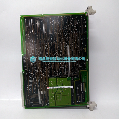
- Product ID: 216EA61b HESG324015R1 KHESG324258R3I HESG448230R1
- Brand: ABB
- Place of origin: The Swiss
- Goods status: new/used
- Delivery date: stock
- The quality assurance period: 365 days
- Phone/WhatsApp/WeChat:+86 15270269218
- Email:stodcdcs@gmail.com
- Tags:216EA61b HESG324015R1KHESG324258R3IHESG448230R1card
- Get the latest price:Click to consult
The main products
Spare parts spare parts, the DCS control system of PLC system and the robot system spare parts,Brand advantage: Allen Bradley, BentlyNevada, ABB, Emerson Ovation, Honeywell DCS, Rockwell ICS Triplex, FOXBORO, Schneider PLC, GE Fanuc, Motorola, HIMA, TRICONEX, Prosoft etc. Various kinds of imported industrial parts
Products are widely used in metallurgy, petroleum, glass, aluminum manufacturing, petrochemical industry, coal mine, papermaking, printing, textile printing and dyeing, machinery, electronics, automobile manufacturing, tobacco, plastics machinery, electric power, water conservancy, water treatment/environmental protection, municipal engineering, boiler heating, energy, power transmission and distribution and so on.

216EA61b HESG324015R1 KHESG324258R3I HESG448230R1 card
This diagnostic test is performed at a rate of 1/s, and takes less than 1 ms. The inability of an input to detect a low or high state during diagnostics, results in the reporting of a fault to the controller, and the flashing of the ACTIVE LED. Digital filtering is performed on all inputs to reduce the occurrence of nuisance faults. Communication between the module and the controller consists of four words. Two words contain the state of each input, and the other two words contain the fault status of each input. Within the state words, a high, or one indicates a ON condition. Within the fault status words, a high, or one indicates a fault at the respective input.module capable of determining the state of switches, relays, solenoids, lamps, proximity switches, and other 24 Vdc powered devices. In addition, the B863–032 monitors itself to insure its ability to detect high or low states at its inputs. This feature is designed to provide an extra margin of reliability in safety shutdown systems. This is accomplished with a module resident diagnostic test. The diagnostics verify the module’s functionality by momentarily forcing all inputs to a low state followed by a high state. This forcing function is transparent to the input source.
Configuration Guidelines
This module appears as a B863 module when configured. This means the module requires four 16–bit words (1x registers), as shown in the data registers diagram below. The first two words contains the state of the input points. The second two words contain the condition of the field wiring. If a broken wire is detected on input point, then a one is displayed in input register (1x+32) at its position. When the fault is fixed, a zero appears in the bit. A one indicates a detected fault, whereas, a zero indicates normal operation of that input point.The B864-001 is an eight-channel register output module with eight 16-bit registers. A channel is defined as a 16-bit data path. The channels can be configured as eight BCD or eight binary registers via the appropriate switch setting. The module is organized in a group strobe arrangement with the 16 datalines associated at a given moment with one of the eight strobe lines. Each strobe line addresses one of the devices on the data bus and enables it to transmit data to a given peripheral device to the exclusion of the other devices. The data lines are routed to all devices. The B864-001is operated in module-select mode. In moduleselect mode, all eight data registers are transferred in a single ourbus cycle. The following is a simplified block diagram of the unit.
Switch Settings
Two toggle switches are located at the top of the module and are used to determine the type of communication with external devices. Both switches are user selectable. 1. Bin/BCD Switch This toggle switch determines whether the output data is to be interpreted by the target devices as a BCD or a binary value. 2. Strobes Active Hi/Lo Switch This toggle switch allows selection of either true-hi or true-lo for strobing output data.User connections are made to a standard screw terminal strip. The rigid wiring system permits module insertion or removal without disturbing the wiring. The following illustration shows how to field connect the unit.The following illustration indicates how the resistors are connected at the device end.For a single device consisting of 16 data lines, 16 1 k resistors are required, or, one 1 k resistor/data line. As additional devices are added to the data bus, the value of the pull-up resistor must be increased by 1 k. In other words, if two devices are used, the pull-up resistor must be 2 k, three devices require a 3 k pull-up, and so on, with the maximum number of 8 devices requiring 8 k of pull-up for each data line.