Home > Product > DCS control system > GDB021BE GDB021BE01 HIEE300766R0001 controller card
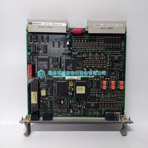
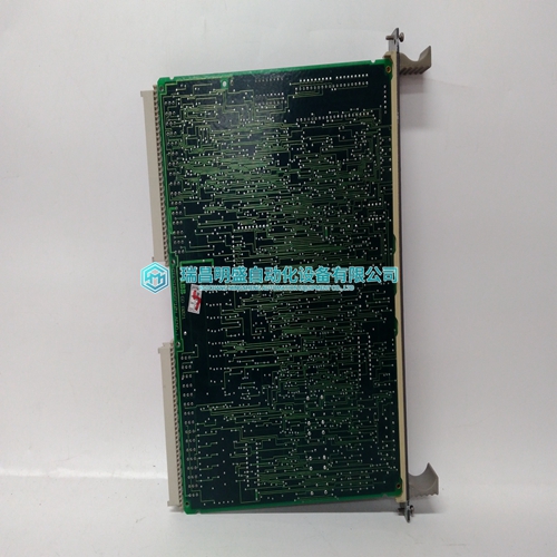
GDB021BE GDB021BE01 HIEE300766R0001 controller card
- Product ID: GDB021BE GDB021BE01 HIEE300766R0001
- Brand: ABB
- Place of origin: The Swiss
- Goods status: new/used
- Delivery date: stock
- The quality assurance period: 365 days
- Phone/WhatsApp/WeChat:+86 15270269218
- Email:stodcdcs@gmail.com
- Tags:GDB021BE GDB021BE01HIEE300766R0001controller card
- Get the latest price:Click to consult
The main products
Spare parts spare parts, the DCS control system of PLC system and the robot system spare parts,Brand advantage: Allen Bradley, BentlyNevada, ABB, Emerson Ovation, Honeywell DCS, Rockwell ICS Triplex, FOXBORO, Schneider PLC, GE Fanuc, Motorola, HIMA, TRICONEX, Prosoft etc. Various kinds of imported industrial parts
Products are widely used in metallurgy, petroleum, glass, aluminum manufacturing, petrochemical industry, coal mine, papermaking, printing, textile printing and dyeing, machinery, electronics, automobile manufacturing, tobacco, plastics machinery, electric power, water conservancy, water treatment/environmental protection, municipal engineering, boiler heating, energy, power transmission and distribution and so on.

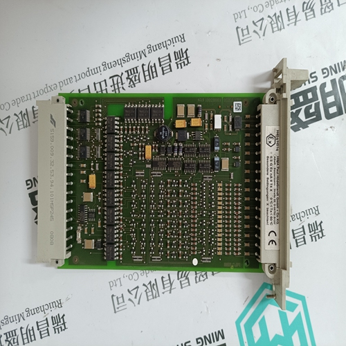
GDB021BE GDB021BE01 HIEE300766R0001 controller card
Two toggle switches are located at the top left of the module and are used to determine the type of communication with external devices. Both switches are user selectable. 1. Bin/BCD Switch This toggle switch determines whether the output data is to be interpreted by the target devices as a BCD or a binary value. 2. Strobes Active Hi/Lo Switch This toggle switch allows selection of either true-hi or true-lo for strobing output data.The module can operate in either BCD or binary mode. The desired mode is userselectable, with the parallel 16-bit input having BCD values in the range 0000 to 9999 and the binary input in the range 0000 (HEX) to FFFF (HEX). The B869-002 is an 8 channel device that operates in a channel select mode. In the channel select mode, only one channel (16-bit register width) is transferred during each cycle. This is accomplished by employing a simple form of handshaking with the PC. A channel select word is sent by the PC to the module, requesting data from a specific channel. The module then responds by sending the requested data, together with a channel select echo. Channel select mode requires 1 output and 2 consecutive input registers. The output register (Channel Select Reg) contains the address of the selected channel, while the 2 input registers contain the channel number echo and the data, respectively
Schematic Diagram
The B869–002 operates with a 16-bit data path. Data is routed in from a device by means of a strobe line associated with each device. The data lines are common to all devices while the strobe performs the addressing function. The channel select function permits the PC to transfer a single channel of 16 bits from a selected field device to the PC during one OURBUS cycle. The DC (data changing) signal from the field device is used for slowly changing data such as thumb wheel switches and prevents erroneous information from being transferred to the PLC. To avoid loading the bus when a device is not being addressed, any active device interfaced to the input module must have latched, tri-state, or open collector outputs.User connections are made to a standard screw terminal strip. The rigid wiring system permits module insertion or removal without disturbing the wiring. Terminal numbering and input functions are shown on the following illustration
Pull-up Resistor Connection Resistive
pull-ups of 2.2 kΩ ± 10% for each strobe line must be provided.This is required on ACTIVE devices only. Thumb wheel switches, for example, do not require the addition of pull-up resistors. The recommended location for the pull-up resistors is at the device end of the circuit. However, they will work at the module end as well. The following illustration shows a typical circuit setup The B881–001 Latched 24 Vdc Input Module senses and converts input signals from its field circuitry to a logic level used by Modicon PLC. The incoming signal causes the module to latch at the occurrence of the ON state and may be considered a latching event. The 24 Vdc, true high latched input module is capable of direct connection to any Modicon, true high dc output module (at proper voltage). The following illustration shows the B881–001 Latched 24 Vdc Input Module Simplified Block Diagram