Home > Product > PLC programmable module > 1747-L552 Programmable module
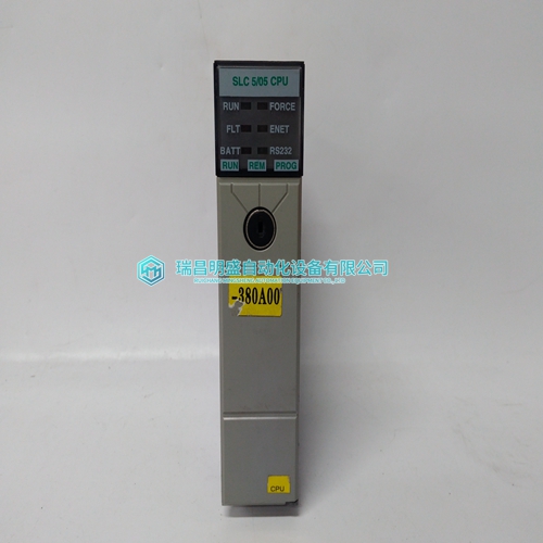
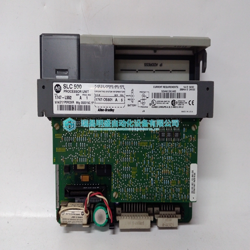
1747-L552 Programmable module
- Product ID: 1747-L552
- Brand: A-B
- Place of origin: the United States
- Goods status: new/used
- Delivery date: stock
- The quality assurance period: 365 days
- Phone/WhatsApp/WeChat:+86 15270269218
- Email:stodcdcs@gmail.com
- Tags:1747-L552Programmable module
- Get the latest price:Click to consult
The main products
Spare parts spare parts, the DCS control system of PLC system and the robot system spare parts,Brand advantage: Allen Bradley, BentlyNevada, ABB, Emerson Ovation, Honeywell DCS, Rockwell ICS Triplex, FOXBORO, Schneider PLC, GE Fanuc, Motorola, HIMA, TRICONEX, Prosoft etc. Various kinds of imported industrial parts
Products are widely used in metallurgy, petroleum, glass, aluminum manufacturing, petrochemical industry, coal mine, papermaking, printing, textile printing and dyeing, machinery, electronics, automobile manufacturing, tobacco, plastics machinery, electric power, water conservancy, water treatment/environmental protection, municipal engineering, boiler heating, energy, power transmission and distribution and so on.

1747-L552 Programmable module
User connections are made to a standard screw terminal strip. The rigid wiring system permits module insertion or removal without disturbing the wiring. Setting the DIP switch allows selection of bi-directional fault reporting or uni-directional nonfault reporting functionality prior to installation. The following illustration shows the B882–032 terminal numbering and output connections
The four-position dip switch is located on the rear of the module. This switch controls the functionality of the module (bi-directional or uni-directional). Set switch SW3 for either (B882) bi-directional fault reporting, or (B818) unidirectional non-fault reporting. Refer to the following illustration for switch settings. Also refer to the label located on the left side of the module itself. The following illustration shows the B882–032 dip switch settings Note: Selecting the bi-directional module functionality(B882) allows 32 discrete outputs and 32 returned fault flags. Selecting the uni-directional module functionality (B818) allows 32 discrete outputs.
B882–116 24 Vdc Output, Configuration
This module appears as a B882 module when configured—i.e., the module requires either four 16-bit words—two 3x input registers and two 4x holding registers or 32 discrete 0x outputs and 32 discrete 1xinputs. The first holding register contains the command state programmed by the user. The input registers contains the faults detected. If an open circuit fault is detected on output point three, then a one is displayed in the 3x register at position three. If a short fault is detected on output point three, then a one is displayed in register 3x + 1 at position three. A one indicates a detected fault, whereas a zero indicates normal operation of that output point. The module uses only three of the four configured 16-bit words. A point that is shorted disables the output current flow. Once a fault is detected the operation follows the following flow chart if the module is in the pulse test mode of operation. If not in pulse test mode, then reported faults are cleared when a command changes it to the opposite state. In either case the detection of a short will force the point off.
A two-position dip switch located
on the rear of the module is used to select one of two test modes on a group basis. No pulse test mode detects open circuits only when the output is OFF, and shorts circuits only when the point is ON. Pulse test mode pulses the output to the opposite of the command state to determine the status of the output load. Each individual switch relate s to each group of eight output points. For example, DIP switch position #1 when set to ON enables pulse test fault sensing for group 1(points 1-8). When a fault is detected the corresponding FAULT LED flashes independent of the test mode. When the switch is in the OFF position, no pulse test is performed. The pulse dip-switch settings for the B882–116 module is shown below.
The 24 V field supply must be rated to supply output load current +.5 A for the module, +5 A surge rating. This 5 A surge rating is required to correctly detect short circuits. Group input power fusing is recommended. The fuse should be rated for expected load current plus 5 A slo-blow
