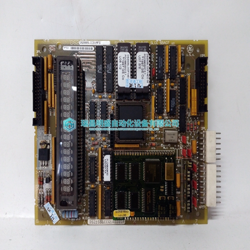
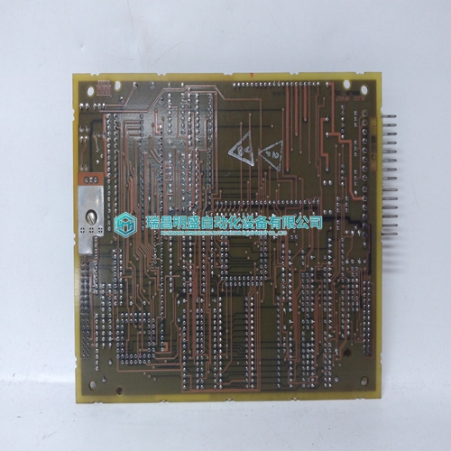
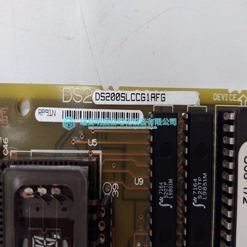
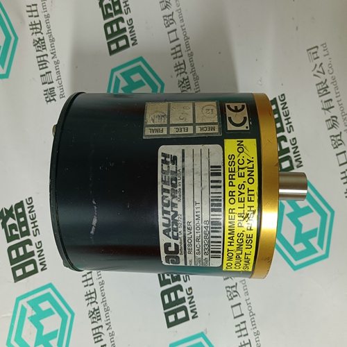
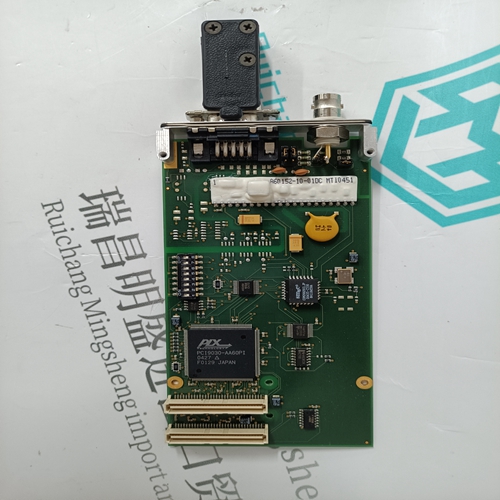
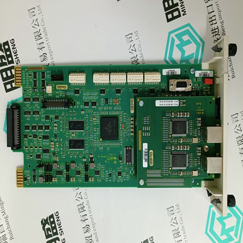
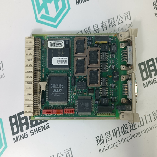
Home > Product > Gas turbine system > DS200SLCCG1AFG DS215SLCCG1AZZ01A module
DS200SLCCG1AFG DS215SLCCG1AZZ01A module
- Product ID: DS200SLCCG1AFG DS215SLCCG1AZZ01A
- Brand: GE
- Place of origin: the United States
- Goods status: new/used
- Delivery date: stock
- The quality assurance period: 365 days
- Phone/WhatsApp/WeChat:+86 15270269218
- Email:xiamen2018@foxmail.com
- Tags:DS200SLCCG1AFGDS215SLCCG1AZZ01Amodule
- Get the latest price:Click to consult
The main products
Spare parts spare parts, the DCS control system of PLC system and the robot system spare parts,Brand advantage: Allen Bradley, BentlyNevada, ABB, Emerson Ovation, Honeywell DCS, Rockwell ICS Triplex, FOXBORO, Schneider PLC, GE Fanuc, Motorola, HIMA, TRICONEX, Prosoft etc. Various kinds of imported industrial parts
Products are widely used in metallurgy, petroleum, glass, aluminum manufacturing, petrochemical industry, coal mine, papermaking, printing, textile printing and dyeing, machinery, electronics, automobile manufacturing, tobacco, plastics machinery, electric power, water conservancy, water treatment/environmental protection, municipal engineering, boiler heating, energy, power transmission and distribution and so on.
DS200SLCCG1AFG DS215SLCCG1AZZ01A module
If the signal [ON/OFF] (901) changes from 1 to 0 (edge sensitive), the drive will block the controllers immediatelly and start a delay time. Because of the regulator blocking the armature and field current will be forced to zero. When the delay time has elapsed the outputs for handling the contactors will be set to 0; the contactors should drop off. This input has the second highest priority. The sequence described before will be worked out independant from the drive condition (with / without speed; with / without armature current). In case of tripping, the fan, field and main contactors are opened in a certain order which depends on the type of the fault. Fault activates the output FAULT (10904) to logical state 1. If a motor or converter overtemperature fault is detected, the outputs for handling the cooling fans are kept high until the measured temperature has decreased below the alarm level. The drive will accept a reset-command, when the temperature has decreased below the fault level. In this case the outputs for the fan contactors will be reset.
OPERATING INSTRUCTION
The input START_INHIBIT] (908) has the highest priority. If this input is set to 1, the outputs for the handling of the contactors can never be forced to level 1, if the drive is at standstill. If the drive is running and the input is set to 1, the drive will act in the same way as if [ON/OFF] (901) is set to 0. Afterwards the drive cannot be switched on as long as START_INHIBIT (908) has logic 1 level. When dynamic braking is used (output DYN BRAKE ON (10912)), an external resistor is connected in parallel with the armature module. If the drive trips, the field of the motor must be maintained, otherwise the resistor cannot produce fast deceleration. Run Control When RDY RUNNING (10901) = 1, the drive can be started by setting either input [RUN1] (901), [RUN2] (902) or [RUN3] (903) to state 1. The drive releases the references and controllers and sets the RUNNING (10903) signal to logical state 1. Another way to start the drive is by Control Panel CDP312 in local mode using the start button.
The drive can be stopped in the following ways:
- By opening the Main Contactor: Controlling [ON/OFF] (901) input to zero state. All contactors will open and there is no electrical braking. The drive will stop by coasting (see opening control of the contactors). This stop mode cannot interrupt Emergency Stop, Stop because of panel or field bus link problems. - RUN-command to zero If all RUN inputs [RUN1] (902), [RUN2] (903) or [RUN3] (904) are set to zero , the drive will stop. This stop mode can be interrupted by Emergency Stop, Stop because of panel or field bus link problems. Parameter STOP MODE (916) defines how the stop is made: 0 = stop by ramp (DECEL1 (1709) or DECEL2 (1712) ) at RAMP GENERATOR function block 1 = stop by torque limit (TORQ_MAX / TORQ_MIN) 2 = stop by coasting (torque is zero)
