Home > Product > Robot control system > SAIA PCD1.M120 Automation module
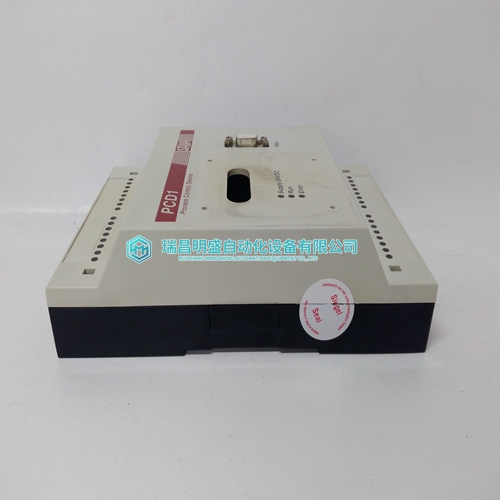
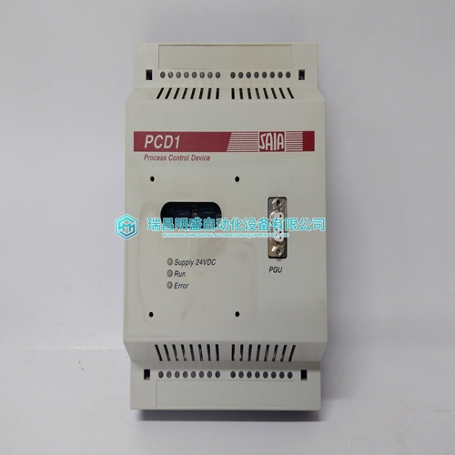
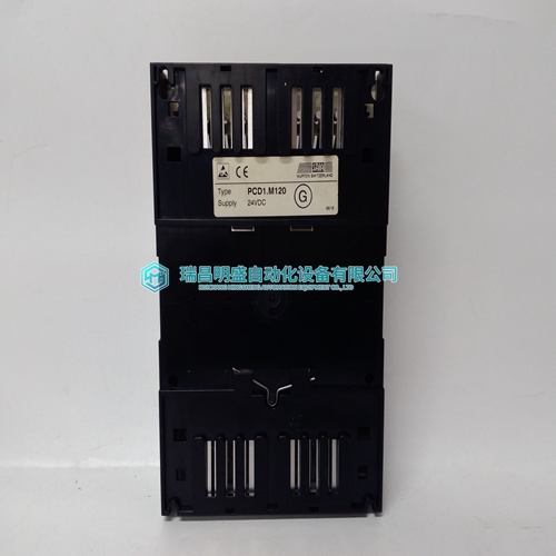
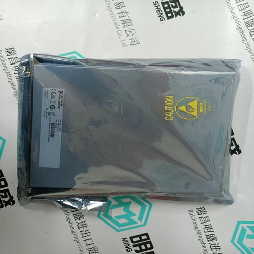
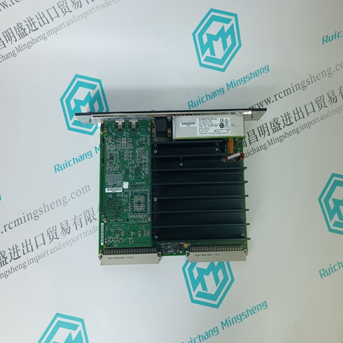
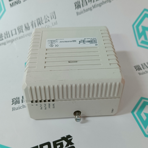
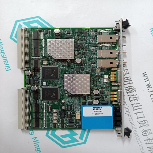
SAIA PCD1.M120 Automation module
- Product ID: PCD1.M120
- Brand: SAIA
- Place of origin: the United States
- Goods status: new/used
- Delivery date: stock
- The quality assurance period: 365 days
- Phone/WhatsApp/WeChat:+86 15270269218
- Email:stodcdcs@gmail.com
- Tags:SAIAPCD1.M120Automation module
- Get the latest price:Click to consult
The main products
Spare parts spare parts, the DCS control system of PLC system and the robot system spare parts,Brand advantage: Allen Bradley, BentlyNevada, ABB, Emerson Ovation, Honeywell DCS, Rockwell ICS Triplex, FOXBORO, Schneider PLC, GE Fanuc, Motorola, HIMA, TRICONEX, Prosoft etc. Various kinds of imported industrial parts
Products are widely used in metallurgy, petroleum, glass, aluminum manufacturing, petrochemical industry, coal mine, papermaking, printing, textile printing and dyeing, machinery, electronics, automobile manufacturing, tobacco, plastics machinery, electric power, water conservancy, water treatment/environmental protection, municipal engineering, boiler heating, energy, power transmission and distribution and so on.
SAIA PCD1.M120 Automation module
The drive can be reset using the input [RESET] (907) or in local control mode by means of the control panel CDP312 by pressing the RESET-button. The drive recognises the rising edge of the signal. To be able to restart the drive after trip, there has to be a rising edge in signal ON/OFF-input . The technique prevents the RESETinput signal from self-commanding the contactors "ON".
The DCS 500B software can be discussed from different point of views, depending what is wanted. Within chapter 1 the features are listed by their functionallity. If this functionallity needs to be used at probably two different applications, it is more useful to have a look to the internal structure of the software. The drive control program is subdivided into 3 blocks: - parameter set 1 for parameter groups 1 to 24 - parameter set 2 for parameter groups 1 to 24 - application set for parameter groups 25 The Drive can be controlled either in Remote state by means of the digital inputs or in Local state by the CDP312 control panel or the CMT/DCS500 Commissioning and Maintenance Tool. LOCAL (10906) output is in logical state 1, if LOCAL-mode is selected.
Speed feedback and speed reference handling
The speed feedback signals can be taken from three different sources: • by means of analog tacho generator • by means of a pulse encoder • from the EMF signal, calculated by the converter by means of the converter´s output voltage The speed reference for speed control can be given in several ways: • by means of analog input • from a constant reference source • reference up/down counter • application program • CDP312 panel or CMT/DCS500 Tool Speed scaling to software The speed values (ref./act.) are scaled so that 20000 units in software equals to the drive's maximum speed which is set in parameter SPEED SCALING (2103) in 0.1 rpm accuracy. For example, maximum speed is 1000 rpm. SPEED SCALING would be set to 10000. When speed reference is 10000, the motor runs at 500 rpm. The maximum value of the speed reference is -30000 or +30000 depending on which direction of rotation is used.
SPEED_MEASURME NT function block
The speed of the motor can be measured in three different ways: by an incremental encoder, by an analogue tacho generator or by a calculated/measured EMF-voltage. Speed measurement with the pulse encoder has four different modes. The difference between these modes is in the accuracy of the measurement, which depends on the type of pulse encoder. The analogue tacho generator is connected to the analogue input channel AITAC. The input voltage range is -10V...+10V and accuracy of A/D-conversion is 13 bits. If higher than 10V tacho generator is used, the scaling of incoming voltage can be done on I/Oboard SDCS-IOB-1 and in case of I/O-board SDCS-IOB-3 with external circuits (PS5311). The software of the DCS 500B includes scaling parameters for adjusting the analogue speed feedback.
