Home > Product > DCS control system > VE3007 12P4375X032 KJ2005X1-BA1 Control module
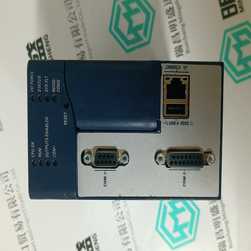
VE3007 12P4375X032 KJ2005X1-BA1 Control module
- Product ID: VE3007 12P4375X032 KJ2005X1-BA1
- Brand: EMERSON
- Place of origin: The United States
- Goods status: new/used
- Delivery date: stock
- The quality assurance period: 365 days
- Phone/WhatsApp/WeChat:+86 15270269218
- Email:stodcdcs@gmail.com
- Tags:VE3007 12P4375X032KJ2005X1-BA1Control module
- Get the latest price:Click to consult
The main products
Spare parts spare parts, the DCS control system of PLC system and the robot system spare parts,Brand advantage: Allen Bradley, BentlyNevada, ABB, Emerson Ovation, Honeywell DCS, Rockwell ICS Triplex, FOXBORO, Schneider PLC, GE Fanuc, Motorola, HIMA, TRICONEX, Prosoft etc. Various kinds of imported industrial parts
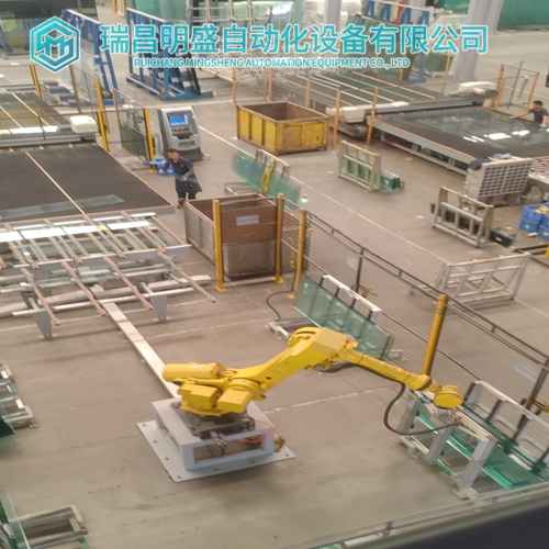
Products are widely used in metallurgy, petroleum, glass, aluminum manufacturing, petrochemical industry, coal mine, papermaking, printing, textile printing and dyeing, machinery, electronics, automobile manufacturing, tobacco, plastics machinery, electric power, water conservancy, water treatment/environmental protection, municipal engineering, boiler heating, energy, power transmission and distribution and so on.
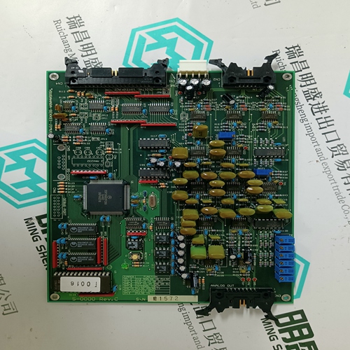
VE3007 12P4375X032 KJ2005X1-BA1 Control module
Depending on the application and the type of converter (2 or 4 quadrant type) the final configuration is different: - at 2 quadrant systems: the 12-pulse function block remains unchanged; the current reference is taken out of the master and feed to the slave via analog output – input; see separate documentation MASTER – FOLLOWER 1.1 - at 4 quadrant systems: the 12-pulse function block is used; the parameters need to be set and the pins need to be connected; see separate documentation DCS 500 Planning and Startup for 12 Pulse Power Converters DCS500B also includes a datalogger for measurements. Data logger has six logging channels. The capacity of each channel is 1000 samples.
The capacity of each channel is 1000 samples. These channels can be used to collect fast incidents from the DCS500B within a certain time. The total collection time (1...1000s) can be set with a sampling interval parameter DLOG.SAMPL INT (610) (1...1000ms). This collection time is common for all the channels.
Channels can be examined in graph/numeric
form with the CMT/DCS500 Tool. Selection of the parameter/signal index to be sampled in the data logger channels 1...6 is made by setting the index to the desired connection point DLOG1.[IN] (601) ... DLOG6.[IN] (606). Selection of the trigger condition is made by means of the parameter DLOG.TRIGG COND (607) as follows: 0 = external triggering 1 = fault + external triggering 2 = triggers when the difference between two successive values of data logger channel 1 is larger than the value defined in DLOG TRIGG VALUE (608) 3 = triggers when the value in data logger channel 1 exceeds the value which is defined in DLOG TRIGG VALUE (608) 4= triggers when the value in data logger channel 1 falls below the value which is defined in DLOG TRIGG VALUE (608). Note! Function blocks can be used to generate more complex triggering conditions.
The data logger is used to monitor
the speed difference during a speed response test. The measurement points are [STEP] (2002), STEP RESP (12003). Triggering will take place when [STEP] (2002) exceeds the set limit e.g. 10 (given step e.g. 100). Settings: DLOG1.[IN] (601) connect to 2002 DLOG2.[IN] (602) connect to 12003 DLOG.TRIGG COND (607) = 2, triggers when the difference between two successive values of data logger channel 1 is larger than the value defined in DLOG.TRIGG VALUE (608). DLOG.TRIGG VALUE (608) = 10 DLOG.TRIGG DELAY (609) = 800 200 samples before and 800 samples after the triggering. DLOG.SAMPL INT (610) = 3ms, samples are taken 0.6 s (200*3ms) before and 2.4 s (800*3ms) after triggering. Resolution must be observed in setting of the sample interval; a too long interval causes losses in the waveform during fast changes of the measured signal. The status of data logger can be read out from parameter DLOG STATUS (10601). 0 = logger is empty 1 = logger is collecting data