Home > Product > DCS control system > SSA-G1018-0652 switches
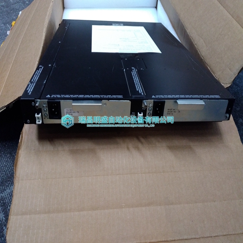
SSA-G1018-0652 switches
- Product ID: SSA-G1018-0652
- Brand: Enterasys
- Place of origin: The United States
- Goods status: new/used
- Delivery date: stock
- The quality assurance period: 365 days
- Phone/WhatsApp/WeChat:+86 15270269218
- Email:stodcdcs@gmail.com
- Tags:SSA-G1018-0652switches
- Get the latest price:Click to consult
The main products
Spare parts spare parts, the DCS control system of PLC system and the robot system spare parts,Brand advantage: Allen Bradley, BentlyNevada, ABB, Emerson Ovation, Honeywell DCS, Rockwell ICS Triplex, FOXBORO, Schneider PLC, GE Fanuc, Motorola, HIMA, TRICONEX, Prosoft etc. Various kinds of imported industrial parts
Products are widely used in metallurgy, petroleum, glass, aluminum manufacturing, petrochemical industry, coal mine, papermaking, printing, textile printing and dyeing, machinery, electronics, automobile manufacturing, tobacco, plastics machinery, electric power, water conservancy, water treatment/environmental protection, municipal engineering, boiler heating, energy, power transmission and distribution and so on.

SSA-G1018-0652 switches
To measure the controller ground connection, do the following: • Measure the resistance of the connection to the ground stud on the 9100 processor base unit, it must be less than 0.2 ?. If it is above this figure then check the ground stud connection. Check Analogue Input Module Calibration Values The AADvance controller detects possible calibration drift by continually checking its measured input values. The controller uses diverse hardware to compare two measurements. It is recommended that you do this calibration drift check every two years. You can make sure that an analogue input is within the stated accuracy (±0.05mA) without taking a module out of service using the following procedure: 1. Use the AADvance® Workbench software or AADvance®-Trusted® SIS Workstation software to lock the input channel. • The input value freezes, allowing the procedure to continue operating. 2. Disconnect the field device at the termination assembly and connect a calibrated current simulation instrument in its place. 3. Set the current simulation instrument to supply 4 mA, make sure that the input value is in the range 3.95 mA to 4.05 mA. 4. Set the current simulation instrument to supply 12 mA, make sure that the input value is in the range 11.95 mA to 12.05 mA.
Check Digital Input Module Calibration Values
The AADvance controller detects possible calibration drift by continually checking its measured input values. The controller uses diverse hardware to compare two measurements. It is recommended that you do this calibration drift test every two years. You can make sure that a digital input is in the stated accuracy (0.5 V) without taking a module out of service. To test the digital input module calibration, do the following: 1. Use the AADvance Workbench software or AADvance-Trusted SIS Workstation software to lock the input channel. • The field input value freezes, allowing the procedure to continue operating. 2. Disconnect the field device at the termination assembly and connect a bench power supply and a calibrated digital voltmeter in its place. 3. Set the bench power supply to give 2 V, make sure that the input value is in the range 1.5 V to 2.5 V. 4. Set the bench power supply to give 16 V, make sure that the input value is in the range 15.5 V to 16.5 V. 5. Set the bench power supply to give 30 V, make sure that the input value is in the range 29.5 V to 30.5 V. 6. Disconnect the test equipment and connect the field device. 7. Apply a minimum tightening torque of 0.5 Nm (0.37 ft. lb.) to the terminal screws. 8. Make sure that the field device is showing a satisfactory value. 9. Unlock the input channel. • The input is in service again.
Perform the Manual Test
The manual test checks for hidden failures of components which the AADvance controller alarms cannot indicate. Do the following: • Transition each digital input to its opposite state and then back to its current state. Subject each analogue input to its full range (minimum to maximum) and examine accuracy. • At the same time, make sure that each output operates as expected. Use the application software to force the outputs which do not seem to operate. • Carry out a manual examination to test each input and output.Rockwell Automation issues firmware upgrades for processor modules from time to time. This chapter provides an overview of the firmware upgrade process and the instructions for using the ControlFLASH™ software.1. Select the Equipment View tab. 2. Select the desired configuration node. This is Config4 (9000 Series Controller) in the example shown below. 3. Select the Version Information tab. • The version information window appears. If the version data has previously been requested and saved (applied) then it will be displayed in this window.