Home > Product > DCS control system > 5X00062G01 5X00063G01 Analog output card
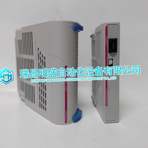
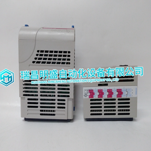
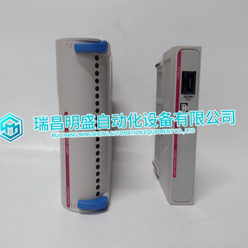
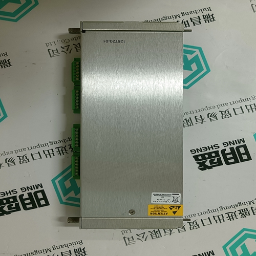
5X00062G01 5X00063G01 Analog output card
- Product ID: 5X00062G01 5X00063G01
- Brand: EMERSON
- Place of origin: The United States
- Goods status: new/used
- Delivery date: stock
- The quality assurance period: 365 days
- Phone/WhatsApp/WeChat:+86 15270269218
- Email:stodcdcs@gmail.com
- Tags:5X00062G015X00063G01Analog output card
- Get the latest price:Click to consult
The main products
Spare parts spare parts, the DCS control system of PLC system and the robot system spare parts,Brand advantage: Allen Bradley, BentlyNevada, ABB, Emerson Ovation, Honeywell DCS, Rockwell ICS Triplex, FOXBORO, Schneider PLC, GE Fanuc, Motorola, HIMA, TRICONEX, Prosoft etc. Various kinds of imported industrial parts
Products are widely used in metallurgy, petroleum, glass, aluminum manufacturing, petrochemical industry, coal mine, papermaking, printing, textile printing and dyeing, machinery, electronics, automobile manufacturing, tobacco, plastics machinery, electric power, water conservancy, water treatment/environmental protection, municipal engineering, boiler heating, energy, power transmission and distribution and so on.
5X00062G01 5X00063G01 Analog output card
All jumpers and switches marked User Configurable in the following tables may be changed or modified by the user. All jumpers marked factory configured should not be modified by the user. Care must be taken when making jumper modifications to ensure against improper settings or connections. Improper settings may result in damage to the unit. Modifying jumper or switches not marked “User Configurable” will void the Warranty and may damage the unit. The default condition of the VMIVME-7700 is expressed in Table 1-1 through Table 1-7 with bold text in the table cells.
The BIOS has the capability (not currently enabled) of password protecting casual access to the unit’s CMOS set-up screens. The Password Clear jumper allows the user to clear the password in the case of a forgotten password. To clear the CMOS password: 1. Turn off power to the unit. 2. Momentarily short the pins of E1 for approximately five seconds. 3. Power up the unit. When power is reapplied to the unit, the CMOS password will be cleared.
Power Requirements
The VMIVME-7700 requires +5V, +12V and -12V from the VMEbus backplane. Below are the voltage and current requirements. Supply Current (Typical) Current (Maximum) +5V 4.0A 5.4A +12V Less than 1mA -12V Less than 1mA The VMIVME-7700 provides power to the PMC site in accordance with the PMC specification. The maximum current provided on the +5V supply is 1.5A per PMC site. The maximum current provided on the +3.3V supply is 1.5A per PMC site. The +12V and -12V supplies are provided to the PMC site and to the rear-transition board (such as the ACC-0562 board). The total +12v or -12v current provided to the VMIVME-7700 (as indicated above), the PMC site and the rear-transition board must not exceed 750mA each, in accordance with the VMEbus Specification.The VMIVME-7700 conforms to the VMEbus physical specification for a single slot 6U Eurocard (dual height). It can be plugged directly into any standard chassis accepting this type of board.
The following steps describe the VMIC
recommended method for VMIVME-7700 installation and power-up: 1. Make sure power to the equipment is off. 2. Choose chassis slot. The VMIVME-7700 must be attached to a dual P1/P2 VMEbus backplane. If the VMIVME-7700 is to be the VMEbus system controller, choose the first VMEbus slot. If a different board is the VMEbus system controller, choose any slot except slot one. The VMIVME-7700 does not require jumpers for enabling/disabling the system controller function. NOTE: Air flow requirements as measured at output side of heatsink is to be greater than 350LFM. 3. Connect all needed peripherals to the front panel. Each connector is clearly labeled on the front panel, and detailed pinouts are in Appendix A. Minimally, a keyboard and a monitor are required if the user has not previously configured the system. 4. Apply power to the system. Several messages are displayed on the screen, including names, versions and copyright dates for the various BIOS modules on the VMIVME-7700. 5. The VMIVME-7700 features a Flash Disk resident on the board. Refer to Chapter 3 for set up details. 6. If an external drive module is installed, the BIOS Setup program must be run to configure the drive types. See Appendix C to properly configure the system. 7. If a drive module is present, install the operating system according to the manufacturer’s instructions. See Appendix D for instructions on installing VMIVME-7700 peripheral driver software during operating system installation.