Home > Product > DCS control system > TRICONEX 8311N Industrial power card
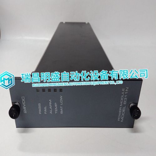
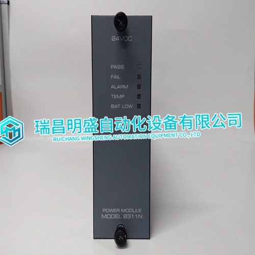
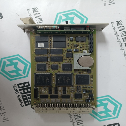
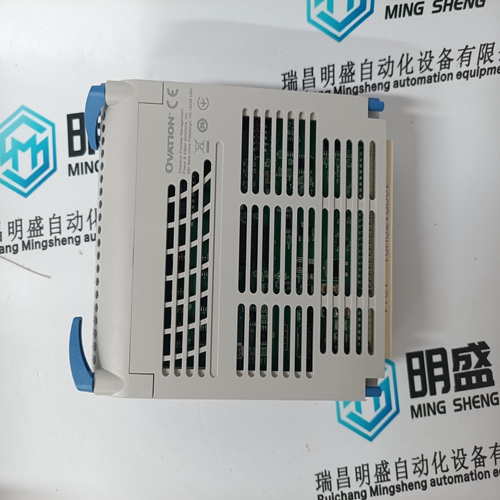
TRICONEX 8311N Industrial power card
- Product ID: 8311N
- Brand: TRICONEX
- Place of origin: The United States
- Goods status: new/used
- Delivery date: stock
- The quality assurance period: 365 days
- Phone/WhatsApp/WeChat:+86 15270269218
- Email:xiamen2018@foxmail.com
- Tags:TRICONEX8311NIndustrial power card
- Get the latest price:Click to consult
The main products
Spare parts spare parts, the DCS control system of PLC system and the robot system spare parts,Brand advantage: Allen Bradley, BentlyNevada, ABB, Emerson Ovation, Honeywell DCS, Rockwell ICS Triplex, FOXBORO, Schneider PLC, GE Fanuc, Motorola, HIMA, TRICONEX, Prosoft etc. Various kinds of imported industrial parts
Products are widely used in metallurgy, petroleum, glass, aluminum manufacturing, petrochemical industry, coal mine, papermaking, printing, textile printing and dyeing, machinery, electronics, automobile manufacturing, tobacco, plastics machinery, electric power, water conservancy, water treatment/environmental protection, municipal engineering, boiler heating, energy, power transmission and distribution and so on.
TRICONEX 8311N Industrial power card
To maintain backward compatibility with PC/XT systems, IBM chose to use the new IRQ9 input on the slave PIC to operate as the old IRQ2 interrupt line on the PC/XT Expansion Bus. Thus, in AT systems, the IRQ9 interrupt line connects to the old IRQ2 pin (pin B4) on the AT Expansion Bus (or ISA bus).Interrupts on Peripheral Component Interconnect (PCI) Local Bus are optional and defined as “level sensitive,” asserted low (negative true), using open drain output drivers. The assertion and de-assertion of an interrupt line, INTx#, is asynchronous to CLK. A device asserts its INTx# line when requesting attention from its device driver. Once the INTx# signal is asserted, it remains asserted until the device driver clears the pending request. When the request is cleared, the device de-asserts its INTx# signal. PCI defines one interrupt line for a single function device and up to four interrupt lines for a multifunction device or connector. For a single function device, only INTA# may be used while the other three interrupt lines have no meaning. Figure 2-1 on page 51 depicts the VMIVME-7700 interrupt logic pertaining to VME operations and the PMC site.
I/O Port Map
Like a desktop system, the VMIVME-7700 includes special input/output instructions that access I/O peripherals residing in I/O addressing space (separate and distinct from memory addressing space). Locations in I/O address space are referred to as ports. When the CPU decodes and executes an I/O instruction, it produces a 16-bit I/O address on lines A00 to A15 and identifies the I/O cycle with the M/I/O control line. Thus, the CPU includes an independent 64 Kbyte I/O address space, which is accessible as bytes, words or longwords. Standard hardware circuitry reserves only 1,024 byte of I/O addressing space from I/O $000 to $3FF for peripherals. All standard PC I/O peripherals, such as serial and parallel ports, hard and floppy drive controllers, video system, real-time clock, system timers and interrupt controllers are addressed in this region of I/O space. The BIOS initializes and configures all these registers properly; adjusting these I/O ports directly is not normally necessary.
System Interrupts
In addition to an I/O port address, an I/O device has a separate hardware interrupt line assignment. Assigned to each interrupt line is a corresponding interrupt vector in the 256-vector interrupt table at $00000 to $003FF in memory. The 16 maskable interrupts and the single Non-Maskable Interrupt (NMI) are listed in Table 2-3 along with their functions. Table 2-4 on page 47 details the vectors in the interrupt vector table. The interrupt number in HEX and decimal are also defined for real and protected mode in Table 2-4 on page 47. The interrupt hardware implementation on the VMIVME-7700 is standard for computers built around the PC architecture, which evolved from the IBM PC/XT. In the IBM PC/XT computers, only eight interrupt request lines exist, numbered from IRQ0 to IRQ7 at the PIC. The IBM PC/AT computer added eight more IRQx lines, numbered IRQ8 to IRQ15, by cascading a second slave PIC into the original master PIC. IRQ2 at the master PIC was committed as the cascade input from the slave PIC. This architecture is represented in Figure 2-1 on page 51.