Home > Product > DCS control system > A4H124-24FX P0973JN switches
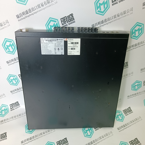


A4H124-24FX P0973JN switches
- Product ID: A4H124-24FX P0973JN
- Brand: FOXBORO
- Place of origin: The United States
- Goods status: new/used
- Delivery date: stock
- The quality assurance period: 365 days
- Phone/WhatsApp/WeChat:+86 15270269218
- Email:stodcdcs@gmail.com
- Tags:A4H124-24FX P0973JNswitches
- Get the latest price:Click to consult
The main products
Spare parts spare parts, the DCS control system of PLC system and the robot system spare parts,
Brand advantage: Allen Bradley, BentlyNevada, ABB, Emerson Ovation, Honeywell DCS, Rockwell ICS Triplex, FOXBORO, Schneider PLC, GE Fanuc, Motorola, HIMA, TRICONEX, Prosoft etc. Various kinds of imported industrial parts
A4H124-24FX P0973JN switches
MemDuration Time during which the power direction last determined remains valid. Receive Input for the signal from the opposite end of the line: T: not used xx: all binary inputs (or outputs of protection functions). Ext Block F: not blocked xx: all binary inputs (or outputs of protection functions). Trip Tripping signal. Start Pick-up signal. Start R R phase pick-up signal. Start S S phase pick-up signal. Start T T phase pick-up signal. MeasFwd signals measurement in the forwards direction. MeasBwd signals measurement in the backwards direction.
E. Setting instructions Settings: Base current IB-Setting Characteristic enabling current I-Start Type of characteristic c-Setting Multiplier k1-Setting Characteristic angle Angle Delay Delay Time allowed for receipt of signal tWait Response at the end of the memorised power direction time MemDirMode Time during which the memorised direction is valid MemDuration Base current “IB-Setting” A tripping current is not set on an IDMT overcurrent function as it is on a definite time overcurrent function. Instead the position of the characteristic is chosen such that it is above the load current. The function, however, has a “base current” setting which is set to the full load current IB1 of the protected unit. The base current setting determines the position of the basic characteristic. The characteristic is enabled when the base current is exceeded by a preset amount (I-Start). The adjustment of the base current IB to the load current IB1 of the protected unit instead of its rated current enables for IB1 < rated current of prot. unit : more sensitive protection IB1 > rated current of prot. unit : maximum utilisation of the thermal capability of the protected unit.
Multiplier ‘k1-Setting’
The multiplier ‘k1-Setting’ enables the IDMT characteristic chosen by the setting of parameter c to be shifted without changing its shape. This is used for grading the operating times of a series of IDMT relays along a line to achieve discrimination. For example, in the case of the “very inverse” characteristic, the constant c = 1 and the factor k1 13.5. The operating time t is given by the equation
An alternative is to adjust the position of the IDMT characteristic to match the rated load of the protected unit and set the base current to its rated current instead of its load current. Enabling the characteristic ‘I-Start’ The IDMT characteristic is enabled when the current exceeds the setting ‘I-Start’. A typical setting for ‘I-Start’ is 1.1 IB. Choice of characteristic ‘c-Setting’ The constant ‘c-Setting’ determines the shape of the IDMT characteristic. The settings for the standard characteristics according to B.S. 142 are: “normal inverse” : c = 0.02 “very inverse” and “long time earth fault” : c = 1.00 “extremely inverse”