Home > Product > Servo control system > KOLLMORGEN E33NRHA-LNN-NS-00 Servo motor
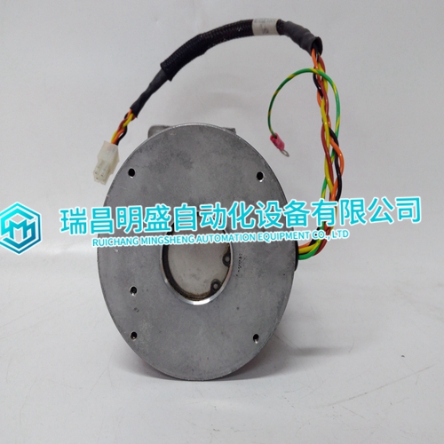
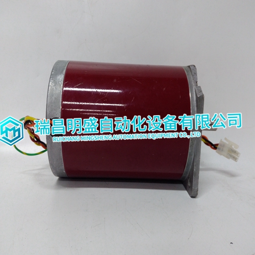
KOLLMORGEN E33NRHA-LNN-NS-00 Servo motor
- Product ID: E33NRHA-LNN-NS-00
- Brand: KOLLMORGEN
- Place of origin: the United States
- Goods status: new/used
- Delivery date: stock
- The quality assurance period: 365 days
- Phone/WhatsApp/WeChat:+86 15270269218
- Email:xiamen2018@foxmail.com
- Tags:KOLLMORGENE33NRHA-LNN-NS-00Servo motor
- Get the latest price:Click to consult
The main products
Spare parts spare parts, the DCS control system of PLC system and the robot system spare parts,Brand advantage: Allen Bradley, BentlyNevada, ABB, Emerson Ovation, Honeywell DCS, Rockwell ICS Triplex, FOXBORO, Schneider PLC, GE Fanuc, Motorola, HIMA, TRICONEX, Prosoft etc. Various kinds of imported industrial parts
Products are widely used in metallurgy, petroleum, glass, aluminum manufacturing, petrochemical industry, coal mine, papermaking, printing, textile printing and dyeing, machinery, electronics, automobile manufacturing, tobacco, plastics machinery, electric power, water conservancy, water treatment/environmental protection, municipal engineering, boiler heating, energy, power transmission and distribution and so on.
KOLLMORGEN E33NRHA-LNN-NS-00 Servo motor
The Timer 4 IRQ Clear (T4IC) register is used to clear an interrupt caused by Timer 4. Writing to this register, located at offset 0x3C from the address in BAR2, causes the interrupt from Timer 4 to be cleared. This can also be done by writing a “0” to the appropriate “Timer x Caused IRQ” field of the timer Control Status Register (CSR1). This register is write only and the data written is irrelevant.The VMIVME-7700 provides a programmable Watchdog Timer (WDT) which can be used to reset the system if software integrity fails.The “SERR/RST Select” bit is used to select whether the WDT generates an SERR# on the local PCI bus or a system reset. If this bit is set to “0”, the WDT will generate a system reset. Otherwise, the WDT will make the local PCI bus SERR# signal active.
The “WDT Enable” bit is used to enable the Watchdog Timer function. This bit must be set to “1” in order for the Watchdog Timer to function. Note that since all registers default to zero after reset, the Watchdog Timer is always disabled after a reset. The Watchdog Timer must be re-enabled by the application software after reset in order for the Watchdog Timer to continue to operate. Once the Watchdog Timer is enabled, the application software must refresh the Watchdog Timer within the selected timeout period to prevent a reset or SERR# from being generated. The Watchdog Timer is refreshed by performing a write to the WDT Keepalive register (WKPA). The data written is irrelevant.
WDT Keepalive Register (WKPA)
When enabled, the Watchdog Timer is prevented from resetting the system by writing to the WDT Keepalive Register (WKPA) located at offset 0x0C from the address in BAR2 within the selected timeout period. The data written to this location is irrelevant.The VMIVME-7700 provides 32KBytes of non-volatile SRAM. This memory is mapped in 32K of address space starting at the address in BAR1. This memory is available at any time and supports byte, short word and long word accesses from the PCI bus. The contents of this memory is retained when the power to the board is removed.The VMIVME-7700 features an optional on-board Compact Flash mass storage system with a capacity of up to 512 Mbyte. This Flash Disk appears to the user as an intelligent ATA (IDE) disk drive with the same functionality and capabilities as a “rotating media” IDE hard drive. The VMIVME-7700 BIOS includes an option to allow the board to boot from the Flash Disk.
Configuration
The Flash Disk resides on the VMIVME-7700 as the secondary IDE bus master device (the secondary IDE bus slave device is not assignable). The default setting in the Phoenix BIOS ‘STANDARD CMOS SETUP’ screen is the ‘AUTO’ setting. In the Phoenix BIOS ‘PERIPHERAL SETUP’ screen, the secondary PCI IDE interface must be enabled for the Flash Disk to be functional. Refer to Appendix C for additional details. The Primary and Secondary PCI IDE Interfaces are controlled (enabled or disabled) in the Integrated Peripheral Setup screen of the Phoenix BIOS. The First Boot Device is selected in the BIOS Features Setup screen. A bootable device is one on which an operating system has been installed, or formatted as a system disk using MS-DOS.The Flash Disk performs identically to a standard IDE hard drive. Reads and writes to the device are performed using the same methods, utilizing DOS command line entries or the file managers resident in the chosen operating system

