Home > Product > PLC programmable module > MVI56-MNETC Redundant module
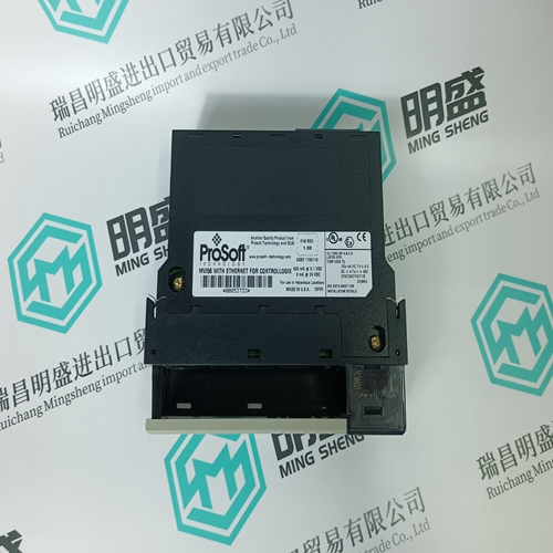
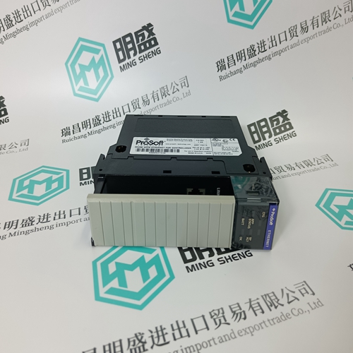
MVI56-MNETC Redundant module
- Product ID: MVI56-MNETC
- Brand: PROSOFT
- Place of origin: the United States
- Goods status: new/used
- Delivery date: stock
- The quality assurance period: 365 days
- Phone/WhatsApp/WeChat:+86 15270269218
- Email:stodcdcs@gmail.com
- Tags:MVI56-MNETCRedundant module
- Get the latest price:Click to consult
The main products
Spare parts spare parts, the DCS control system of PLC system and the robot system spare parts,
Brand advantage: Allen Bradley, BentlyNevada, ABB, Emerson Ovation, Honeywell DCS, Rockwell ICS Triplex, FOXBORO, Schneider PLC, GE Fanuc, Motorola, HIMA, TRICONEX, Prosoft etc. Various kinds of imported industrial parts
MVI56-MNETC Redundant module
Assuming a grading time of 0.5 s at 6 times the base current IB is required, the factor k1 for each of the relays is given by k1 = 5 t. This produces for operating times between 0.5 and 2.5 s the following settings for k1:The characteristics according to BS 142 are set as follows: “normal inverse” : k1 = 0.14 s “very inverse” : k1 = 13.5 s “extremely inverse” : k1 = 80 s “long time earth fault” : k1 = 120 s.Characteristic angle Determining the phase-angle of the current provides an additional criterion for preserving discrimination compared with nondirectional overcurrent protection. The directional sensitivity is 180° in relation to the reference voltage. This is illustrated in the following diagrams. The angles given apply for connection according to the diagram in Section 4.4.2.
The function determines the power direction by measuring the phase-angle of the current in relation to the opposite phase-tophase voltage. Which current is compared with which voltage can be seen from the following table.The voltage measurement automatically compensates the group of connection of the v.t’s. For example, the phase-to-phase values are calculated for Y-connected v.t’s (v.t. type UTS), while the input voltages are used directly for delta-connected v.t’s (v.t. type UTD).
Time allowed for a signal to be received
Where directional functions are configured in both line terminals, each can send a signal from its “MeasBwd” output to the “Receive” input of the function at the opposite end of the line (e.g. via a PLC channel) when it is measuring a fault in the reverse direction. This signal prevents the respective directional overcurrent function from tripping, because the fault cannot be in the zone between them. The functions therefore have to allow time, i.e. the “wait time”, for the signal from the opposite line terminal to be received. If none is received within “tWait”, the circuitbreakers are tripped at both ends. RE. 216 1MDU02005-EN / 3 / Änd. I ABB Switzerland Ltd 3.5.5-11 The time set for “Delay” acts in this kind of scheme as a backup which does not rely on the communication channel. Thus when the “Receive” input is being used, the setting for “Delay” must be longer than the setting for “tWait”: “Delay” > “tWait”.