Home > Product > DCS control system > EPRO MMS6120 Speed sensor
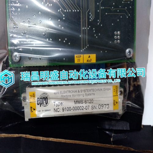
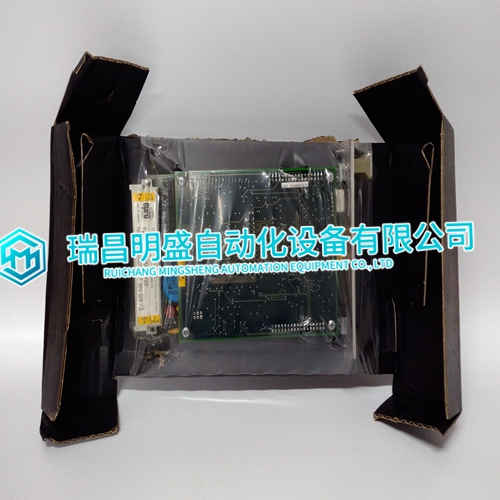
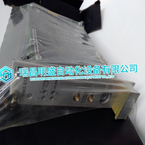
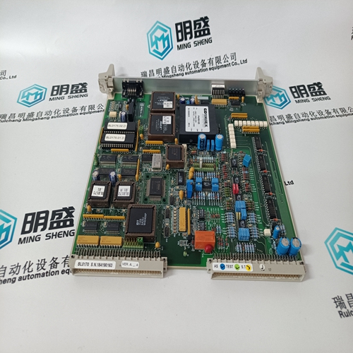
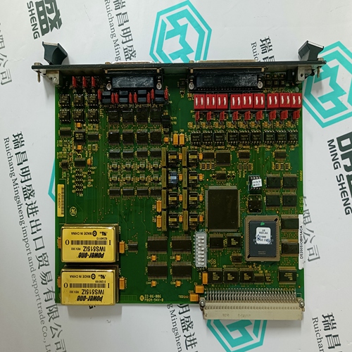
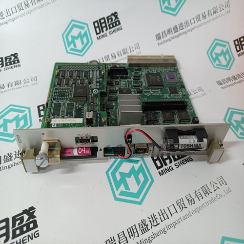
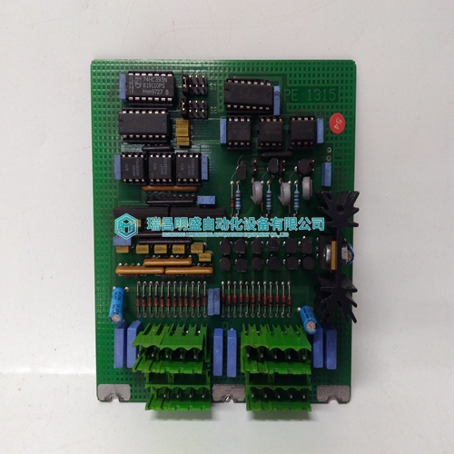
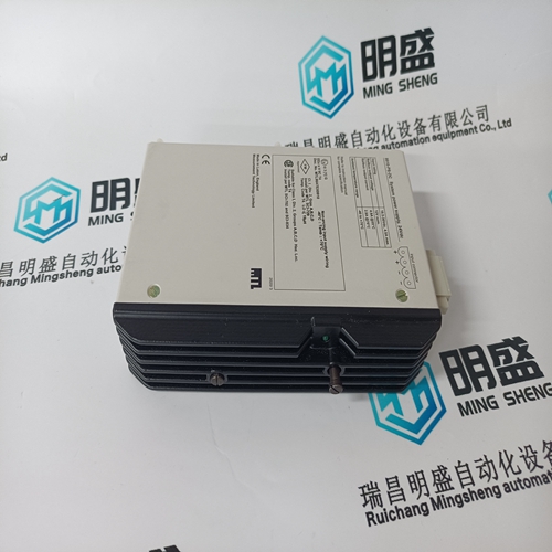
EPRO MMS6120 Speed sensor
- Product ID: MMS6120
- Brand: EPRO
- Place of origin: The United States
- Goods status: new/used
- Delivery date: stock
- The quality assurance period: 365 days
- Phone/WhatsApp/WeChat:+86 15270269218
- Email:stodcdcs@gmail.com
- Tags:EPROMMS6120Speed sensor
- Get the latest price:Click to consult
EPRO MMS6120 Speed sensor
A "type" fault is annunciated through the application program when the wrong module type is installed at a given address. For example, installing a thermocouple module in place of an RTD module generates a type fault. If an output node receives data intended for a different module type, it will not update its outputs, and will set them to the "off" state when its watchdog timer times out. No message faults, address faults, and type faults are non-latching. When these faults occur for an input module, the application program will give default values for each channel. Troubleshooting Flowchart If a problem occurs with the LINKnet network, use Figure 11-25 (Troubleshooting Flowchart) as a guide to find and repair the problem.The LINKnet 6 Channel Analog Output (AO) Module provides six 4-20 mA analog outputs. The output current is monitored by the module processor through an A/D converter. The read back value and status are available through the application program. The 4-20 mA output module has a watchdog that monitors the communications from the module processor to the D/A converter, and disables the current drivers upon a loss of communications of more than 1.2 seconds.
Install the LINKnet 6CH Analog Output Module
on the DIN rail and connect to the appropriate LINKnet network and 24 Vdc power. Wire the analog outputs per Figure 11-19. Set module address one’s and ten’s rotary switches per application setup. The LINKnet system accommodates hot-replacement of faulty nodes. When replacing a node, the network cable connections must remain intact. A faulty node can be removed from the network by pulling both terminal blocks out of their headers, and removing the node from the DIN rail. The address switches of the replacement node should be set to match those of the faulty node. The replacement node can then be mounted on to the DIN rail, and the terminal blocks pushed into the headers. It is then necessary to reset the node through the application program to reinitiate communications with the LINKnet controller module and to clear the "no message" fault.The fault LED denotes the status of the module processor, and will be off during normal operation. If the fault LED is on or is blinking, and cycling power to the module does not change it, then the I/O module should be replaced.
The 4-20 mA output module
processor receives information through the transceiver, from the LINKnet controller module. The 4-20 mA output module then updates the status of the D/A converter which outputs voltages to the current drivers. The output current is monitored by the module processor through an A/D converter. The read back value and status are available through the application program. The 4-20 mA output module has a watchdog that monitors the communications from the module processor to the D/A converter, and disables the current drivers upon a loss of communications of more than 1.2 seconds. The module will not function after a watchdog timeout until its power is cycled or the MicroNet system is reset. See Figure 11-20 for block diagram of the 4-20 mA Output module.
The main products
Spare parts spare parts, the DCS control system of PLC system and the robot system spare parts,
Brand advantage: Allen Bradley, BentlyNevada, ABB, Emerson Ovation, Honeywell DCS, Rockwell ICS Triplex, FOXBORO, Schneider PLC, GE Fanuc, Motorola, HIMA, TRICONEX, Prosoft etc. Various kinds of imported industrial parts
Products are widely used in metallurgy, petroleum, glass, aluminum manufacturing, petrochemical industry, coal mine, papermaking, printing, textile printing and dyeing, machinery, electronics, automobile manufacturing, tobacco, plastics machinery, electric power, water conservancy, water treatment/environmental protection, municipal engineering, boiler heating, energy, power transmission and distribution and so on.
