Home > Product > DCS control system > PPD115A102 3BHE017628R0102 Control module
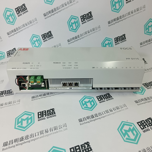
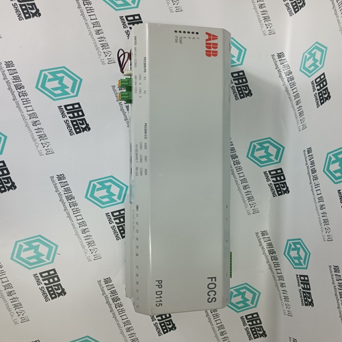
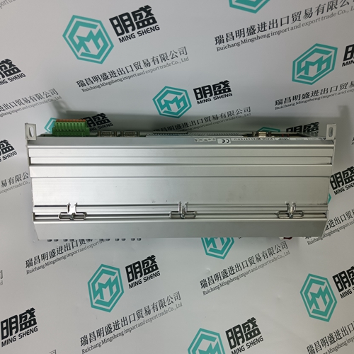
PPD115A102 3BHE017628R0102 Control module
- Product ID: PPD115A102 3BHE017628R0102
- Brand: ABB
- Place of origin: The Swiss
- Goods status: new/used
- Delivery date: stock
- The quality assurance period: 365 days
- Phone/WhatsApp/WeChat:+86 15270269218
- Email:stodcdcs@gmail.com
- Tags:PPD115A102 3BHE017628R0102Control module
- Get the latest price:Click to consult
The main products
Spare parts spare parts, the DCS control system of PLC system and the robot system spare parts,
Brand advantage: Allen Bradley, BentlyNevada, ABB, Emerson Ovation, Honeywell DCS, Rockwell ICS Triplex, FOXBORO, Schneider PLC, GE Fanuc, Motorola, HIMA, TRICONEX, Prosoft etc. Various kinds of imported industrial parts
PPD115A102 3BHE017628R0102 Control module
As can be seen from Fig. 3.5.10.2, the relay setting for a zone of protection of 95 % is 5 % of Umax. The scheme detects E/F's on the generator stator winding, the cables to the step-up transformer and the delta-connected windings of the step-up transformer. The capacitances between primary and secondary of the step-up transformer conduct currents emanating from E/F's on the HV side to the LV side and can cause false tripping of the stator E/F protection. The capacitive coupling of E/F currents on the HV side takes place regardless of whether the HV star-point is grounded or not. The capacitance C12 between HV and LV windings of the step-up transformer and the capacitance C of the generator circuit form a potential divider, which determines the potential of the generator star-point (see Fig. 3.5.10.3a). The value of the capacitance C is usually too low to definitely hold the star-point below the pick-up setting of the protection. For this reason, the generator star-point is grounded via a resistor RE (see Fig. 3.5.10.4), which ensures that the potential of the starpoint remains below the setting of the protection for an E/F on the HV power system. Correspondingly, the value of the resistor RE is chosen such that for a given C12 and an E/F at the HV terminals of the step-up transformer, the off-set of the generator star-point does not reach the pick-up setting of the 95 % E/F protection.
where:
C12 capacitance between primary and secondary of the step-up transformer C capacitance to ground of the stator windings, the cables with protection capacitors and the LV step-up transformer winding U star-point off-set UOS rated voltage of the step-up transformer HV windings IE E/F current RE grounding resistor The value of the grounding resistor RE determines the E/F current. In view of the damage, which can be caused by an E/F current, especially to the laminations of the stator core, the maximum E/F current should be limited to 20 A for 10 s, i.e. the grounding resistor RE must not be too small. Tripping by the E/F protection is delayed by 0.5 s to avoid any risk of false tripping during transient phenomena. Designing a scheme for connection to the generator star-point 1. Version with grounding resistor and v.t. (see Fig. 3.5.10.4)
where: C12 capacitance between primary and secondary of the step-up transformer C capacitance to ground of the stator windings, the cables with protection capacitors and the LV step-up transformer winding U star-point off-set UOS rated voltage of the step-up transformer HV windings IE E/F current RE grounding resistor The value of the grounding resistor RE determines the E/F current. In view of the damage, which can be caused by an E/F current, especially to the laminations of the stator core, the maximum E/F current should be limited to 20 A for 10 s, i.e. the grounding resistor RE must not be too small. Tripping by the E/F protection is delayed by 0.5 s to avoid any risk of false tripping during transient phenomena. Designing a scheme for connection to the generator star-point 1. Version with grounding resistor and v.t. (see Fig. 3.5.10.4)
