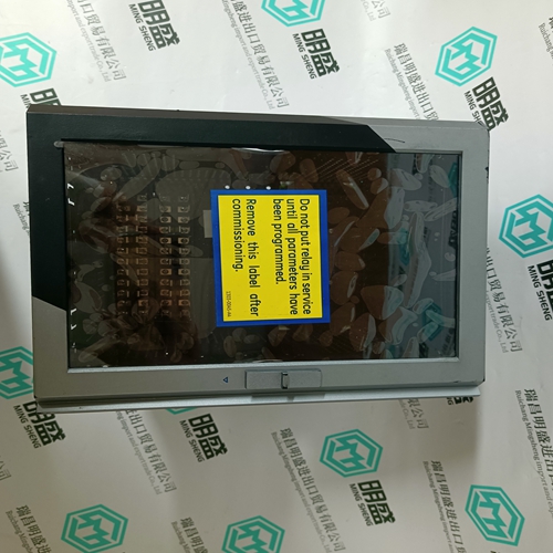
Home > Product > PLC programmable module > 140CPU67160C CPU module
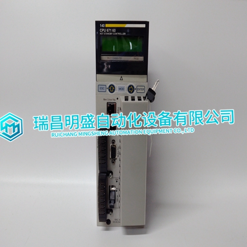
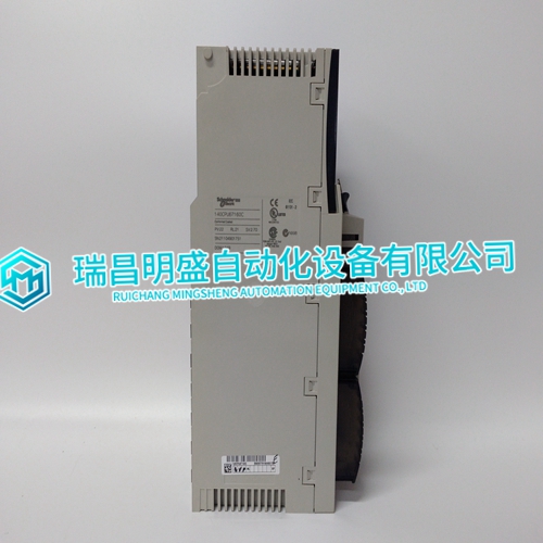
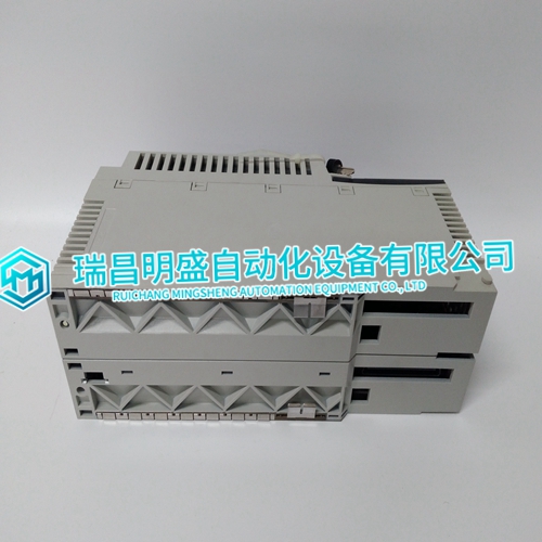
140CPU67160C CPU module
- Product ID: 140CPU67160C
- Brand: 140PLC
- Place of origin: the United States
- Goods status: new/used
- Delivery date: stock
- The quality assurance period: 365 days
- Phone/WhatsApp/WeChat:+86 15270269218
- Email:xiamen2018@foxmail.com
- Tags:140CPU67160CCPU module
- Get the latest price:Click to consult
140CPU67160C CPU module
Miniature circuit breaker (MCB) discrimination studies should be carried out when designing the system power distribution.The graph shows the response of a single Power Module to severe overloads. As the load is increased the power supply protection mechanism operates and shuts down the output. It can be seen that for a period of just in excess of 200 ms the Power Module can provide currents up to 115 A or 380 % of its stated maximum(115/31 = 3.8). This 200 ms/380 % can be extrapolated for additional power supplies in order to perform MCB discrimination studies.Active power factor correction circuitry ensures that this Power Pack meets the requirements of IEC 61000-3-2.When using this table to calculate cable feed requirements, allow, at a minimum, an extra 3 % for variations between units. Actual measured results will depend upon the harmonic content of the input voltage waveform.
General Description
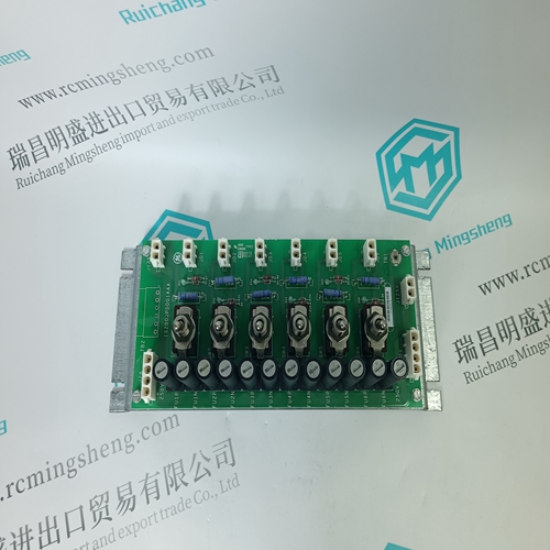
The Power Port is a supplied accessory and is fitted onto the rear of the Power Shelf. It converts alarm signals produced by the Power Packs and Power Shelf into volt-free alarm contacts for use by the system and enables hot replacement of Power Packs. It consists of a PCB fitted with connectors, relays and miscellaneous electronic components. The shape and size of the Power Port is shown in Figure 11.The alarm contacts are made available on a connector for ease of wiring into the system. The system provides a supply for the Power Port, which is wired to the same connector. The connector pin-outs are shown in section 5.3. The Power Shelf is fitted with a 25 way D female connector to which the Power Port connects. The Power Port is retained to the Power Shelf by means of the Dsub jack screws. The Power Port is fitted with a 25 way D female connector to allow the Power Shelf connectivity to be extended to a Power Controller using a Power Shelf Interconnect ribbon cable. The Power Controller is powered from the Power Port 24 V supply via pin 7, when connecting CON 2 on the Power Port to the Power Controller.
Circuit Description
The circuit is split into four functional sections: supply, DC alarms, AC alarms and jumpers. 5.2.1. Supply The 24 V supply is connected to CON3 pins 1 and 6. The supply should be fused close to its source, using a 500 mA F rated fuse. It is nevertheless protected by a non-replaceable fuse on the Power Port. The 24 V is regulated down to 5 V with decoupling provided. The 5 V+ is used to supply the low voltage electronics. The 24 V is used to supply the relays and is connected through CON2 to power the optional Power Controller. 5.2.2. DC Alarms CON1 is the 25 way D male interface to the Power Shelf. The Power Pack and Power Shelf alarm outputs are derived from here. There are two DC alarms per Power Pack: DCFAIL (dc output fail) and OTP (over-temperature protection). The Power Port ORs together DCFAIL and OTP to give one DC fail alarm, via CON 3. If either alarm triggers, the corresponding relay de-energises. Each relay operates a volt-free contact. These are closed when healthy (relay energised) and open in alarm. The contacts share a common return line.
The main products
Spare parts spare parts, the DCS control system of PLC system and the robot system spare parts,
Brand advantage: Allen Bradley, BentlyNevada, ABB, Emerson Ovation, Honeywell DCS, Rockwell ICS Triplex, FOXBORO, Schneider PLC, GE Fanuc, Motorola, HIMA, TRICONEX, Prosoft etc. Various kinds of imported industrial parts
Products are widely used in metallurgy, petroleum, glass, aluminum manufacturing, petrochemical industry, coal mine, papermaking, printing, textile printing and dyeing, machinery, electronics, automobile manufacturing, tobacco, plastics machinery, electric power, water conservancy, water treatment/environmental protection, municipal engineering, boiler heating, energy, power transmission and distribution and so on.
