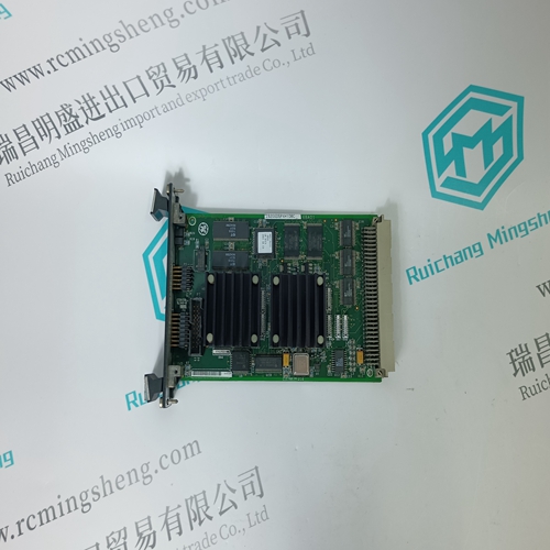
Home > Product > DCS control system > HONEYWELL TK-PRS021 51404305-275 module
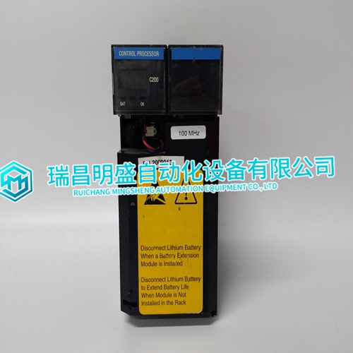
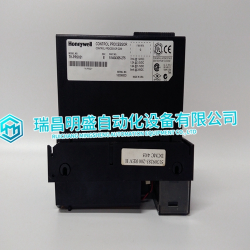
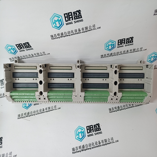
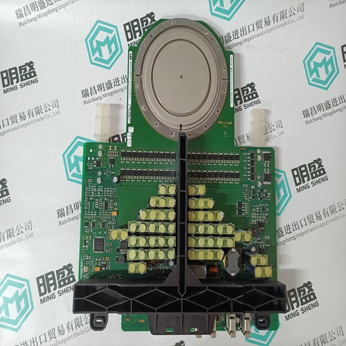
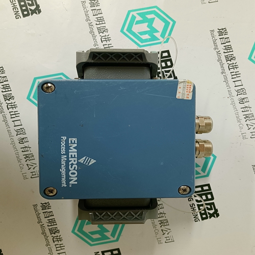
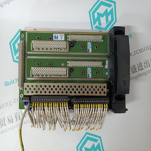
HONEYWELL TK-PRS021 51404305-275 module
- Product ID: TK-PRS021 51404305-275
- Brand: HONEYWELL
- Place of origin: The United States
- Goods status: new/used
- Delivery date: stock
- The quality assurance period: 365 days
- Phone/WhatsApp/WeChat:+86 15270269218
- Email:xiamen2018@foxmail.com
- Tags:HONEYWELLTK-PRS021 51404305-275module
- Get the latest price:Click to consult
HONEYWELL TK-PRS021 51404305-275 module
The URPlus and UR optionally has a color graphic HMI that allows users to have customizable bay diagrams with local monitoring of status, values and control functionality. The alarm annunciator panel provides the configuration of up to 96 (UR) or 256 signals (URPlus) (alarms and status) with full text description. A 7” color, graphic HMI is optionally available that allows users to have customizable bay diagrams with local monitoring of status, values and control functionality. The alarm annunciator panel provides the configuration of up to 96 signals (alarms and status) with full text description.The UR contains many tools and reports that simplify and reduce the amount of time required for troubleshooting power system events, increase uptime and reduce loss of production.Record the operation of the internal UR elements and external connected devices with 1ms time-stamped accuracy to identify the Sequence of Operation of station devices during faults and disturbances.
INTERRUPT SENDER ID REGISTERS (26H, 2AH, 2EH)
The three interrupt sender ID registers contain the ID of the node which originated the interrupt currently being serviced. All data sent across the fiber-optic link is tagged with the ID of the originating node so it may be removed from the link once it has been passed around the link one time. The ID is stored in the appropriate register if the data word received is an interrupt. As part of the interrupt handler software, the user must read the appropriate ID register in order to re-arm the currently used interrupt. This process insures that all interrupts sent to the node will be processed. The user may or may not use the ID but it must be read as part of the interrupt handler process. In the event that a certain interrupt has been masked off at the BIM, the FIFO for that interrupt may be cleared by writing to the ID register for the specific interrupt level before the BIM is armed. The ID write process is to be done in addition to the BIM arming process. In the interrupt handling sequence, the user should do only one read per interrupt cycle. Erroneous results will be caused by multiple reads.
LOCAL STATUS INTERRUPT
The fourth interrupt on the MC68153 (INT0) is dedicated to generate an interrupt in the event that the local FIFOs become half-full or a corrupt transfer has been received. If the interrupt is not disabled, every time the local VMIVME-5576 is written to and the transmit FIFO is over half full or a transfer error occurs, an INT0 will be generated. The half-full information flag is also available by looking at the CSR. If the transmit FIFO is allowed to become full and the FIFO half full is set, a BERR will be generated when a Write is attempted to the VMIVME-5576. Tables 4.9-1 and 4.9-2 show the architecture of MC68153 registers. The corrupt transfer interrupt may be masked off by removing the mask jumper. This is done so the user will not be bothered by interrupts in redundant transfer mode.
The main products
Spare parts spare parts, the DCS control system of PLC system and the robot system spare parts,
Brand advantage: Allen Bradley, BentlyNevada, ABB, Emerson Ovation, Honeywell DCS, Rockwell ICS Triplex, FOXBORO, Schneider PLC, GE Fanuc, Motorola, HIMA, TRICONEX, Prosoft etc. Various kinds of imported industrial parts
Products are widely used in metallurgy, petroleum, glass, aluminum manufacturing, petrochemical industry, coal mine, papermaking, printing, textile printing and dyeing, machinery, electronics, automobile manufacturing, tobacco, plastics machinery, electric power, water conservancy, water treatment/environmental protection, municipal engineering, boiler heating, energy, power transmission and distribution and so on.

