Home > Product > Robot control system > KEBA FM265A Logic control card
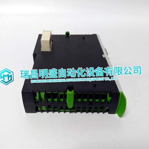
KEBA FM265A Logic control card
- Product ID: FM265A
- Brand: KEBA
- Place of origin: the United States
- Goods status: new/used
- Delivery date: stock
- The quality assurance period: 365 days
- Phone/WhatsApp/WeChat:+86 15270269218
- Email:stodcdcs@gmail.com
- Tags:KEBAFM265ALogic control card
- Get the latest price:Click to consult
KEBA FM265A Logic control card
he speed control box should be mounted on the control panel, often on the same skid as the engine. It is not designed for installation on the engine. Provide space for adjustment, wiring access, and ventilation. Choose a location that protects the control from being bumped and that the wiring harness will reach. The installation should allow for adequate air circulation to the control box and have an ambient temperature of –40 to +75 °C (–40 to +167 °F).Install the magnetic pickup on a rigid bracket or housing so its tip is near an engine-driven gear. This gear must be made of a ferrous material that reacts to a magnetic field. Adjust the MPU for 0.25 to 1.0 mm (0.010 to 0.040 inch) between the gear and the MPU at the closest point. Electrical Connections Connect the system as shown in the appropriate wiring diagram (Figures 1-2, 1-3, 1-4). See the appropriate manual for wiring of accessories. Connect the speed control to system ground.
Shields
Use twisted-pair, shielded wire where the wiring diagram shows. Each shield must be grounded only at the end nearest the control. Do not ground both ends of a shield. Tie all shields to the same ground point. When passing a shield through a terminal block, connect the shield to its own terminal. Do not ground the shield at the terminal block. Do not solder to braided shields. CAUTION—BATTERY Damage to the speed control will occur if the battery is disconnected while the alternator or battery charging device is energized and connected to the control.
Installation Check and Troubleshooting
All Units To verify correct system operation after installation and any time trouble occurs, do the following checks in the order given. Disconnect all accessories. Leave the IDLE/RATED switch or jumper connected. On isochronous EPGs, jumper terminal 7 to terminal 8, and terminal 11 to terminal 12. On EPGs with droop, leave terminals 9, 10, 11, and 12 disconnected with CT and PT wires properly secured for safety. On EPGs with dual dynamics, leave terminals 7 and 8 open to select primary (fast) dynamics. If the system does not respond as indicated, find the fault and correct it. 1. Check electrical connections: Correct? Tight? 2. Magnetic Pickup: Correctly adjusted? Tight? Resistance of 50–350 Ω? 3. Close the IDLE/RATED switch (or install a jumper)
The main products
Spare parts spare parts, the DCS control system of PLC system and the robot system spare parts,
Brand advantage: Allen Bradley, BentlyNevada, ABB, Emerson Ovation, Honeywell DCS, Rockwell ICS Triplex, FOXBORO, Schneider PLC, GE Fanuc, Motorola, HIMA, TRICONEX, Prosoft etc. Various kinds of imported industrial parts
Products are widely used in metallurgy, petroleum, glass, aluminum manufacturing, petrochemical industry, coal mine, papermaking, printing, textile printing and dyeing, machinery, electronics, automobile manufacturing, tobacco, plastics machinery, electric power, water conservancy, water treatment/environmental protection, municipal engineering, boiler heating, energy, power transmission and distribution and so on.