Home > Product > DCS control system > IOR810 P-HB-IOR-80010000 power contactor
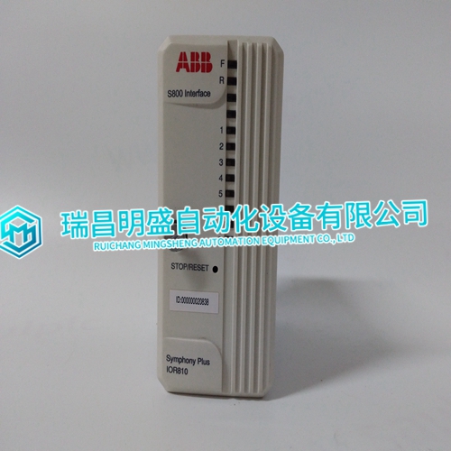
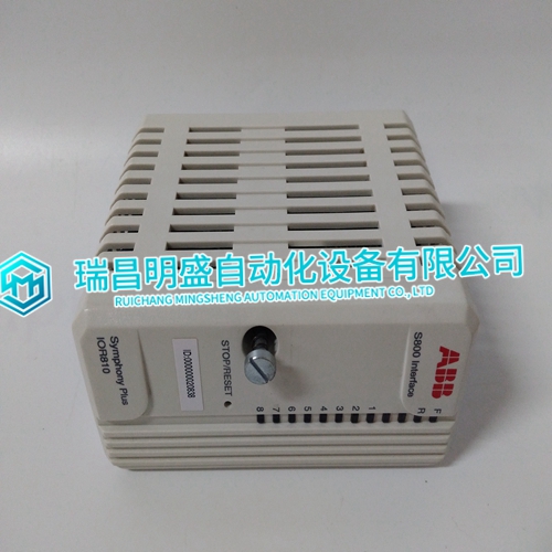
IOR810 P-HB-IOR-80010000 power contactor
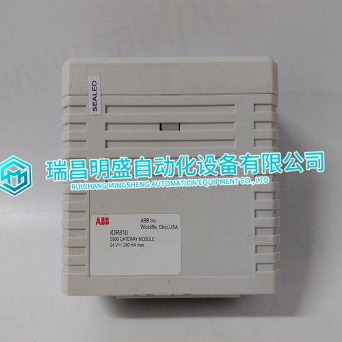
- Product ID: IOR810 P-HB-IOR-80010000
- Brand: ABB
- Place of origin: The Swiss
- Goods status: new/used
- Delivery date: stock
- The quality assurance period: 365 days
- Phone/WhatsApp/WeChat:+86 15270269218
- Email:stodcdcs@gmail.com
- Tags:IOR810P-HB-IOR-80010000power contactor
- Get the latest price:Click to consult
IOR810 P-HB-IOR-80010000 power contactor
The reference block generates accurate 1 VDC and 5 VDC signals. The CIS does not have potentiometers to adjust zero offset and gain for the A/D converter circuits. Instead, the MFP reads the reference voltages once per minute to calibrate the 0 percent (1 VDC) and 100 percent (5 VDC) points; this calibration automatically corrects the measured values. It is performed continuously to correct for drift and temperature variations.The analog output mode switch (S3) sets the type of output, either current or voltage. If current mode is selected, the E/I circuits on the CIS convert the voltage from the D/A converter to a current output. Section 3 explains how to set S3.
Analog Outputs
The D/A converter block is two separate D/A converters. Each D/A converts a 10-bit digital value (analog count) from the MFP to an analog output (1 to 5 VDC). To check module circuit integrity, the outputs are fed back to the analog input section. The feedback values (analog output digital values) are compared to the values that were sent to the analog output section to test the output quality. This tests for an output circuit failure or an open loop between the master module and slave module. The analog output default switch (S2) sets the output values during system start-up or time-out (refer to BUS FAULT TIMER in this section). The analog outputs will go to 0 percent or 100 percent output, or they will hold their current values depending on the setting of S2. Section 3 explains how to set S2.
DIGITAL I/O
The CIS can input three separate digital signals and output four separate digital signals. Digital inputs are voltages of 24 VDC, 125 VDC or 120 VAC. These voltages indicate an energized (ON) field device; a 0 volt input indicates a de-energized (OFF) field device. The CIS digital outputs can switch 24 VDC at 250mA. Figure 2-3 shows the digital input and output circuits.The CIS has two possible propagation (speed) choices for DC inputs to allow for contact debounce time: a slow setting (17 millisecond response time) and a fast setting (1.5 millisecond response time). Jumpers on the CIS select the voltage level and response time for each input. Section 3 explains the jumper connections.
The main products
Spare parts spare parts, the DCS control system of PLC system and the robot system spare parts,
Brand advantage: Allen Bradley, BentlyNevada, ABB, Emerson Ovation, Honeywell DCS, Rockwell ICS Triplex, FOXBORO, Schneider PLC, GE Fanuc, Motorola, HIMA, TRICONEX, Prosoft etc. Various kinds of imported industrial parts
Products are widely used in metallurgy, petroleum, glass, aluminum manufacturing, petrochemical industry, coal mine, papermaking, printing, textile printing and dyeing, machinery, electronics, automobile manufacturing, tobacco, plastics machinery, electric power, water conservancy, water treatment/environmental protection, municipal engineering, boiler heating, energy, power transmission and distribution and so on.